Custom bolts!

On the same day of the first "standing" of Mimas, Merchiston workshop technicians helped us make custom bolts for the Rocker-Bogie: each bolt (threaded rod, more precisely) passes through the suspension tubes and is secured at both ends with washers and nuts. Also, the "bogie" part of the suspension system was moved closer to the "rocker", removing an M8 nut, and replacing it with a big washer.

  • [Hours of work: 1h]
  • [People involved: Giorgio]

enter image description here

"Hey! Look at me, I'm standing on my own!"

After months of testing, printing and assembling, Mimas finally stands on her own wheels! The Rocker-Bogie suspension system is stiff enough to handle the weight of the metal body frame, without plastic or metal deformations. All six wheels stably touch the ground and the differential bar avoids unwanted pitch movements. The suspension system is not fully working yet, since some bolts are still missing. However, it is already possible to test the mechanics that allow the rover to overcome rocks and other obstacles.

  • [Hours of work: 8h]
  • [People involved: Giorgio]

enter image description here

Disassemble and Reassemble.

Some parts of this project are easy to do, and some others are not. Assembling the suspension joints with the relative tubes was an easy job. Disassembling the whole metal structure built several months ago to fit the first half of the suspension system, has been much more complicated. This exercise required several hours of parts fitting and adaptation of 3D-printed parts, to fix the small errors made by the printer. Using advanced engineering techniques (Dremel), all pieces were rounded and snap-fitted in position. One of the subassembly that required more work is the rocker joint, connected to a 21-hours-of-printing part: the rocker base. The insanely high infill percentage (80%) was chosen to allow drilling and other post-printing adaptations, carving an almost-solid material. The first side of the Rocker-Bogie suspension system has been assembled in roughly two hours, slightly customising the 3D-printed parts using the Dremel and a hot soldering iron to melt the plastic.

  • [Hours of work: 2h]
  • [People involved: Giorgio]

enter image description here

The Imager looks around!

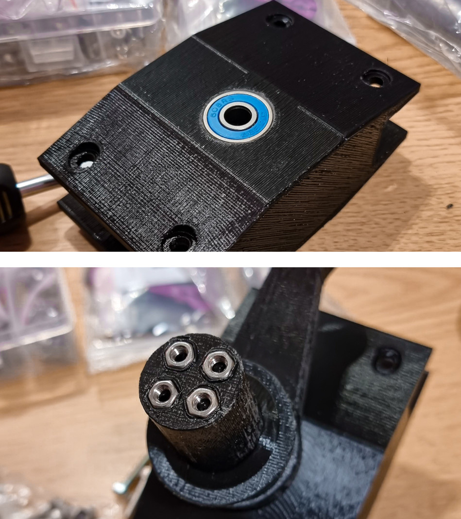
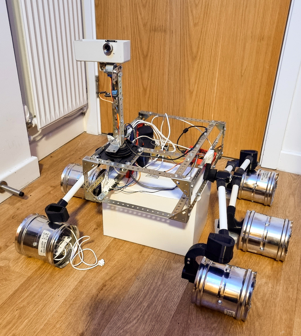
The control system used for Mast Tower v.2 is more or less the same as the one used for Mast Tower v.1. At the base of the structure there is a stepper motor controlled with steps and micro-steps: in Mast Tower v.1, a 4-cables stepper was used, connected to a gear reduction to overcome the lack of potential of the motor (quite damaged due to its second-hand state). Its torque was relatively low, not strong enough to move the heavy metal structure mounted on top of it. In Mast Tower v.2, an 8-cable stepper motor was chosen: the expectation was to take advantage of its heavy weight to add more structural stability to the whole tower. Eventually, it turned out to not be a good option: there isn't much documentation about 8-cable steppers. Initially, the idea was to connect the coils that control the motor rotor, in series; however, a smooth rotational movement was not achieved in a reasonable amount of time. This is the reason why a step back has been taken, substituting the 8-cable stepper with a twin of the 4-cable stepper motor used for Mast Tower V.1. Differently from the 1st twin, the 2nd twin is in perfect condition, so it was possible to ensure a great torque and precision even without a gear reduction. 
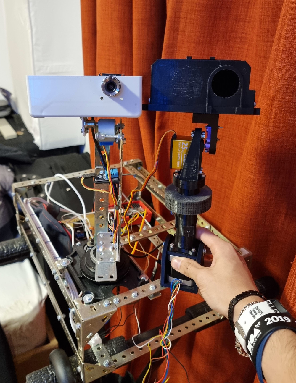
In the end, there was no need to change anything in the code for the pan rotation, since the type of motor used is the same in Mast Tower v.1 and v.2. To ensure a precise tilt rotation, a high-precision servo has been assembled under the cameras housing. It is controlled with a few lines of code, resulting in an overall great upgrade from the first version of the Imager / Mast Tower!

  • [Hours of work: 3h]
  • [People involved: Giorgio]

Mast Tower v.2.

The assembly of Mimas using 3D-printed parts has finally started! Since the first working assembly of the structure made in the summer period was the Imager, that is also what was powered first! The new Mast Tower (hence the Imager) is almost entirely 3D-printed to reduce the weight: the heavier component is the 4-cables stepper motor located at the base. The stepper transfers its motion to the upper section of the tower using an M8 threaded rod connected to the motor pin using a springy metal coupler, allowing pan rotation of the cameras. This not-fully rigid assembly allows the upper section of the Imager to avoid vibrations coming from driving on uneven terrain. On the top of the tower, a 25kg of torque servo motor ensures an extremely stable tilt rotation of the cameras. At the moment, no other sensors are assembled on the Mast Tower, since their casings are still in the designing phase. The structure weight is almost the same as the previous version of the Imager, but the load is better distributed. Due to the modularity of the Python code, it is possible to control it using the same program code for the Mast Tower v.1, with just tiny changes.

  • [Hours of work: 5h]
  • [People involved: Giorgio]

enter image description here

1-side suspension test.

After a few days of waiting, all bearings, bolts and nuts purchased for the rover assembly have been delivered. Fitting all components together took a relatively short time to get the prototype. Further testing will show that the measurements taken at that time were slightly wrong, leading to a not-perfect placing of the rover on the ground. These problems, however, have been fixed immediately after the first test: now this side of the Rocker-Bogie suspension system is ready to drive! Technical notes: all joints are secured with M8 bolts and relative bearings and nuts.

  • [Hours of work: 3h]
  • [People involved: Giorgio]

Melting and Fitting.

Using a budget provided by Napier University to all students of Engineering, some components were purchased to proceed with the assembly of the rover. These parts are mainly bearings, nuts and bolts of different sizes, as well as threaded rods and other minor items. All components have been carefully selected to ensure rock-steady stability for the rover. In order to guarantee a precise fitting, the 3D printed parts already have holes with the actual diameter of the bolts: before starting the printing process, the Horizontal Expansion has been set to -0.1mm, to avoid any possible fitting error due to an over-expansion of the melted plastic. However, a trick was used to improve the fitting even more: all bearings, nuts and bolts purchased were <1mm larger than they should have been: in order to fit them in the correct holes, all metal components were pre-heated and pushed in position using a tin soldering iron (tin soldering iron temperature: 200°C). This technique was used also to fill small cracks and errors due to the 3D printing process: the hot soldering iron was heat-up and used together with a PLA filament; the result is what can be called "plastic soldering". This is clearly visible in the two pictures shown below.

  • [Hours of work: 4h]
  • [People involved: Giorgio]

enter image description here

Scarecraw.

With more the half of the components of the Rocker Bogie suspension system ready, it was attempted an assembly of the parts, in order to obtain (roughly) the shape of the rover. Even if the structure looks almost entirely assembled, all bearings, nuts and bolts are missing, as well as some of the brackets of the steering wheels (LHS of the picture). Despite that, this is the first time the shape of Mimas is clearly visible!

  • [Hours of work: 1h]
  • [People involved: Giorgio]

enter image description here

MOBM and DU.

Mimas autonomous navigation will be managed by several modular units, each of which has a precise role in taking photos, deciding the best direction where to go, and actually activating the motors. All these systems are controlled by the Mobility Manager (MOBM), which takes all input data, ignores the values that are not in an acceptable range, and does value conversions if needed. The MOBM communicates directly with the Drive Unit (DU), providing it with data stored in an SQLite embedded Database. The data producer (path planning algorithm and/or obstacle-avoidance algorithm) releases a high amount of data in a very short time, while the data consumer (DU) is much slower since the rover drives very slowly. SQLite is a great option for this type of system since it is reliable and portable: the algorithm can be moved from one machine to another and it is multiplatform (it runs on common computers like Linux, Windows or macOS machines, or Rasberry Pi).

  • [Hours of work: 3h]
  • [People involved: Giorgio]

enter image description here

Edinburgh SpaceUp Unconference.

SpaceUp Scotland has been a great occasion to meet people and experts interested in Space, rocketry and robotics. I (Giorgio's speaking) had to opportunity to present the "Mimas" project to a Space Scotland representative, ESA Ambassador, and other Professionals, asking for advice and listening to their opinion about the project. In addition, I got some useful advice for my future after graduation. I attended from 10 am to 7 pm. A group photo will be published as soon as it will be realised by SpaceUp.

  • [Hours of attendance: 9h]
  • [People involved: Giorgio]

enter image description here