Silycon casting.

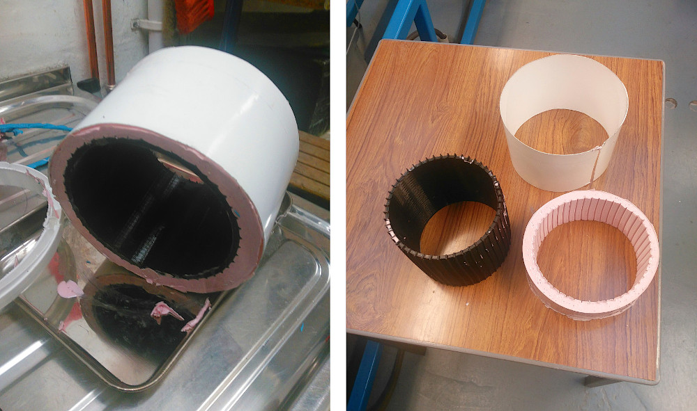
The six wheels have a design inspired by Perseverance wheels: before discussing the choices made for Mimas, it is worthy to briefly analyse the design made by JPL for their rovers. Machined out of a block of flight-grade aluminium and equipped with titanium spokes, each one of the Perseverance's six wheels is slightly larger in diameter and narrower than Curiosity's, with skins that are almost a millimetre thicker. They also feature new treads or grousers: In place of Curiosity's 24 chevron-pattern treads are 48 gently curved ones. For Mimas, steel was used to make a strong and flexible structure with inner suspensions made of bendy but strong steel strips. To obtain the 48 treads, the plan is to use a strong rubber (PU PX60) that will act as a tyre. In reality, rubber and plastic materials are not allowed for travels to Mars, since at very low temperatures, rubber acts as glass, becoming very brittle. Thanks to Lynn Chalmers, the technician for the polymers laboratory at Merchiston Campus, the manufacturing of the six wheels for Mimas can proceed smoothly!

  • [Hours of work: 3h]
  • [People involved: Giorgio, Lynn]

enter image description here

Painting white.

Even though a Mars rover's aesthetics aren't precisely a top concern, success also depends on how the vehicle is painted. White paint may provide a vital reflecting surface for any space-bound item in addition to giving it a simple, clean appearance. And, as John Campanella (the lead painter of Perseverance) said: "any good paint job is preceded by a great tape job". Mars 2020 employed primer and paint that were far from typical of a hardware shop. They have undergone extensive testing to show that they can adhere to aluminium, withstand shocks, vibrations, UV rays, and other annoyances of a trip to Mars, as well as be tough enough to survive the Martian cold, all while not outgassing organic compounds and other materials that could affect the mission's science experiments. On Mimas, the painting used is an enamel paint, a type of paint that air-dries to a hard, giving a glossy finish. It is ideal for coating surfaces that are outdoors or otherwise subject to hard wear or variations in temperature: these characteristics look ideal for the purpose of the project. The photo shown below is the first layer of painting made on the Mast Tower.

  • [Hours of work: 6h]
  • [People involved: Giorgio]

enter image description here

Connectors.

All sensors, motors and other electrical components located outside the Rover's belly, will be connected to the Raspberry Pi4 through cluster cable connectors attached to the WEB. The 3D component shown below can host up to 12 cables: 6 for the wheels on each side of the rover (each DC motor has 2 wires), and 6 for the servo motors located on top of the steering wheels (each servo motor has 3 wires).

  • [Hours of work: 1h]
  • [People involved: Giorgio]

enter image description here

E-MEDA.

The Emulated "Mars Environmental Dynamics Analyzer" also known as E-MEDA makes weather measurements including pressure, temperature and humidity, emulating the sensors used on Perseverance. The temperature sensors are housed in two small Booms structures mounted orthogonal to the Mast Tower of the Rover. For Mimas, two types of sensors were selected: the component shown in the picture above is attached to the Mast through an M3 bolt inserted in the 3D-printed part by melting the plastic. A precise description of the E-MEDA system will be provided in a future update.

  • [Hours of work: 2h]
  • [People involved: Giorgio]

enter image description here

Custom bolts!

On the same day of the first "standing" of Mimas, Merchiston workshop technicians helped us make custom bolts for the Rocker-Bogie: each bolt (threaded rod, more precisely) passes through the suspension tubes and is secured at both ends with washers and nuts. Also, the "bogie" part of the suspension system was moved closer to the "rocker", removing an M8 nut, and replacing it with a big washer.

  • [Hours of work: 1h]
  • [People involved: Giorgio]

enter image description here

"Hey! Look at me, I'm standing on my own!"

After months of testing, printing and assembling, Mimas finally stands on her own wheels! The Rocker-Bogie suspension system is stiff enough to handle the weight of the metal body frame, without plastic or metal deformations. All six wheels stably touch the ground and the differential bar avoids unwanted pitch movements. The suspension system is not fully working yet, since some bolts are still missing. However, it is already possible to test the mechanics that allow the rover to overcome rocks and other obstacles.

  • [Hours of work: 8h]
  • [People involved: Giorgio]

enter image description here

Disassemble and Reassemble.

Some parts of this project are easy to do, and some others are not. Assembling the suspension joints with the relative tubes was an easy job. Disassembling the whole metal structure built several months ago to fit the first half of the suspension system, has been much more complicated. This exercise required several hours of parts fitting and adaptation of 3D-printed parts, to fix the small errors made by the printer. Using advanced engineering techniques (Dremel), all pieces were rounded and snap-fitted in position. One of the subassembly that required more work is the rocker joint, connected to a 21-hours-of-printing part: the rocker base. The insanely high infill percentage (80%) was chosen to allow drilling and other post-printing adaptations, carving an almost-solid material. The first side of the Rocker-Bogie suspension system has been assembled in roughly two hours, slightly customising the 3D-printed parts using the Dremel and a hot soldering iron to melt the plastic.

  • [Hours of work: 2h]
  • [People involved: Giorgio]

enter image description here

The Imager looks around!

The control system used for Mast Tower v.2 is more or less the same as the one used for Mast Tower v.1. At the base of the structure there is a stepper motor controlled with steps and micro-steps: in Mast Tower v.1, a 4-cables stepper was used, connected to a gear reduction to overcome the lack of potential of the motor (quite damaged due to its second-hand state). Its torque was relatively low, not strong enough to move the heavy metal structure mounted on top of it. In Mast Tower v.2, an 8-cable stepper motor was chosen: the expectation was to take advantage of its heavy weight to add more structural stability to the whole tower. Eventually, it turned out to not be a good option: there isn't much documentation about 8-cable steppers. Initially, the idea was to connect the coils that control the motor rotor, in series; however, a smooth rotational movement was not achieved in a reasonable amount of time. This is the reason why a step back has been taken, substituting the 8-cable stepper with a twin of the 4-cable stepper motor used for Mast Tower V.1. Differently from the 1st twin, the 2nd twin is in perfect condition, so it was possible to ensure a great torque and precision even without a gear reduction. In the end, there was no need to change anything in the code for the pan rotation, since the type of motor used is the same in Mast Tower v.1 and v.2. To ensure a precise tilt rotation, a high-precision servo has been assembled under the cameras housing. It is controlled with a few lines of code, resulting in an overall great upgrade from the first version of the Imager / Mast Tower!

  • [Hours of work: 3h]
  • [People involved: Giorgio]

Mast Tower v.2.

The assembly of Mimas using 3D-printed parts has finally started! Since the first working assembly of the structure made in the summer period was the Imager, that is also what was powered first! The new Mast Tower (hence the Imager) is almost entirely 3D-printed to reduce the weight: the heavier component is the 4-cables stepper motor located at the base. The stepper transfers its motion to the upper section of the tower using an M8 threaded rod connected to the motor pin using a springy metal coupler, allowing pan rotation of the cameras. This not-fully rigid assembly allows the upper section of the Imager to avoid vibrations coming from driving on uneven terrain. On the top of the tower, a 25kg of torque servo motor ensures an extremely stable tilt rotation of the cameras. At the moment, no other sensors are assembled on the Mast Tower, since their casings are still in the designing phase. The structure weight is almost the same as the previous version of the Imager, but the load is better distributed. Due to the modularity of the Python code, it is possible to control it using the same program code for the Mast Tower v.1, with just tiny changes.

  • [Hours of work: 5h]
  • [People involved: Giorgio]

enter image description here

1-side suspension test.

After a few days of waiting, all bearings, bolts and nuts purchased for the rover assembly have been delivered. Fitting all components together took a relatively short time to get the prototype. Further testing will show that the measurements taken at that time were slightly wrong, leading to a not-perfect placing of the rover on the ground. These problems, however, have been fixed immediately after the first test: now this side of the Rocker-Bogie suspension system is ready to drive! Technical notes: all joints are secured with M8 bolts and relative bearings and nuts.

  • [Hours of work: 3h]
  • [People involved: Giorgio]