What's new on Continuity Rover?
I'm constantly working on Continuity, taking photos, videos and general notes on (almost) every new thing. If you want to be up to date with what's new, this is the right place!
From Bandits to SPARCbandit: Toward Interpretable Learning
In May, development efforts shifted from low-level control to high-level policy learning, with the design and formalisation of SPARCbandit: a lightweight, explainable reinforcement learning agent tailored for planetary exploration. What began in late 2024 as a series of experiments with contextual multi-armed bandits evolved into a formal proposal and implementation framework suitable for conference submission. SPARCbandit - short for Stochastic Planning & AutoRegression Contextual Bandit - was designed to address the limitations of previous contextual bandit implementations. Where earlier versions were reactive and short-sighted, SPARCbandit introduced several critical features:
- Eligibility Traces (TD(λ)) to propagate credit over time, enabling the agent to associate delayed rewards with prior decisions.
- Adaptive Cost Tracking, using a baseline and autoregressive deviation filter to account for energy consumption, sensor drift, and terrain variance.
- Latching Mechanism, allowing user-specified action preferences (e.g., preferred gaits) to remain in contention despite short-term suboptimality.
- Planning via Dyna-style Updates, where real experiences are augmented with simulated transitions from a learned one-step model.
- Action Selection with Cost-Aware Filtering, combining exploration (ε-greedy) and robustness under non-stationary conditions.
These features were incorporated into SPARCbandit v16, the most stable and refined version of the architecture to date. It supported both sequential learning (TD updates) and bandit-style decision-making, with Q-values parameterised using linear functions over Fourier basis features for interoperability. At the same time, I began preparing the associated conference paper for iSpaRo 2025, outlining the theoretical motivation, implementation details, and performance benchmarks of SPARCbandit. The emphasis was not on raw performance - Deep RL models would outperform it in that domain - but rather on transparency, resource-awareness, and deployability on constrained hardware like the Raspberry Pi 4 aboard Continuity. By the end of May, the core implementation had been tested on benchmark environments such as LunarLander and adapted to my own simulation framework. The algorithm showed stability, robustness to noise, and meaningful cost-sensitive behaviour - all while retaining traceable decision logic, which is essential for real-world deployment in mission-critical systems.
Modeling Attitude Control in Microgravity
Building on earlier empirical and simulation-based work, this month focused on defining the mathematical model that describes how internal leg movements can influence the robot's global orientation in microgravity. The system was modelled as a non-holonomic free-floating body, with no external torque or fixed base. As in the classic falling cat problem, reorientation must emerge entirely from internal actuation - specifically, coordinated changes in the robot's limb configuration. The body was described with 6 DoF, but control efforts focused on roll (ϕ) and pitch (θ). Each leg has 2 DoF (extension and swing), giving 8 independent inputs. Using this, the control problem was defined as an underdetermined linear system, where the Jacobian:

maps joint velocities to changes in roll and pitch rates:
A Constraint-Aware Bandit
In February, the control architecture for Continuity took a substantial step forward with the formal integration of the bandit-based decision layer into the QuectoFSM state machine framework. This was the first implementation of what I termed Constrained Local Learning (CLL): a structure where bandit-based exploration is actively gated by contextual rules, and actions are only permitted when predefined safety and state conditions are satisfied. The multi-armed bandit (MAB) component, now in version 3, moved beyond basic reward selection and hard-coded action cycling. Instead of optimising only low-level parameters (e.g., step height or cycle duration), the new system could also select from a list of gait patterns, each encoded as an arm with an associated performance history. To regulate instability, the bandit’s reward function was overhauled. The original inverse formulation:

was replaced by a log-scaled penalty system, better suited for sharply discouraging large attitude deviations while maintaining sensitivity around small corrections:

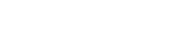
Virtual Actuators and Inertial Reorientation
 Watch: Closed Kinematics Loop problem, old VS new approach
In January, I revisited one of the earliest and most persistent simulation challenges: the closed kinematic chain used in each of Continuity’s legs. URDF lacks native support for closed loops, and PyBullet's rigid body solver struggles with stability when constraints are not explicitly enforced. Previous attempts relied on “fake” revolute joints between femurs and tibias, but these caused instability, especially under dynamic movement, with the robot occasionally entering oscillatory or jumping states. After extensive debugging and physical intuition testing, I adopted a hybrid constraint approach. The solution involved modelling the leg’s closed geometry indirectly via a set of virtual actuators: each tibia’s angle was no longer explicitly controlled, but derived as a function of its corresponding femur's motion using precomputed constants:

This mimicked the effect of parallel bars closing the linkage while retaining numerical stability. The result was a marked reduction in unintended vertical impulses and more consistent leg trajectories across the gait cycle.
Reorientation and Bandit-Based Autonomy
 Watch: Self-reorientation attempt using Contextual MAB
During November and December, the project's focus shifted toward a more abstract - but mission-critical - aspect of legged mobility: attitude control and self-reorientation in microgravity conditions. While locomotion on uneven terrains remained a long-term goal, this phase initiated the development of strategies for reorienting a free-floating rigid body using only internal leg motions, without relying on external contacts or torque sources. This involved modelling Continuity as a non-holonomic system in microgravity, where angular momentum is conserved, and reorientation must occur through the redistribution of internal masses - specifically, the four legs. The problem setup mirrors the classical "falling cat" scenario, where a free-floating body must execute sequences of internal movements to rotate in space despite zero net external torque.
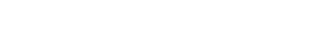
Procedural Terrain Generation in PyBullet
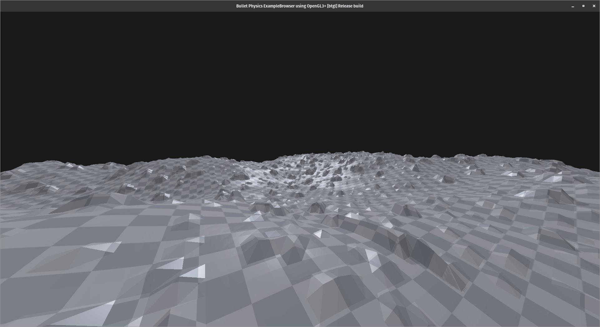
The focus throughout October was on developing a modular terrain generation system within the PyBullet simulation environment. The objective was to build a procedural framework capable of generating diverse terrain types - mountain ranges, valleys, craters, plains, and rocky surfaces - with enough control to vary scale, resolution, and density parameters. Initial prototypes used heightmaps based on Perlin noise and Gaussian distributions to approximate elevation profiles. These methods enabled controllable roughness and large-scale features, with post-processing filters used to either smooth or exaggerate sharpness. To simulate realistic planetary surfaces (e.g. lunar and martian conditions), additional logic was added to introduce crater depressions and scattered rock formations. These could be toggled or adjusted parametrically to study how different environments impact robot behaviour and locomotion strategies. The terrain generator was structured as a standalone Python module, allowing batch generation of terrains with predefined seeds for reproducibility. Each generated terrain could be loaded directly into PyBullet, with optional physics materials for friction, restitution, and compliance tuning.
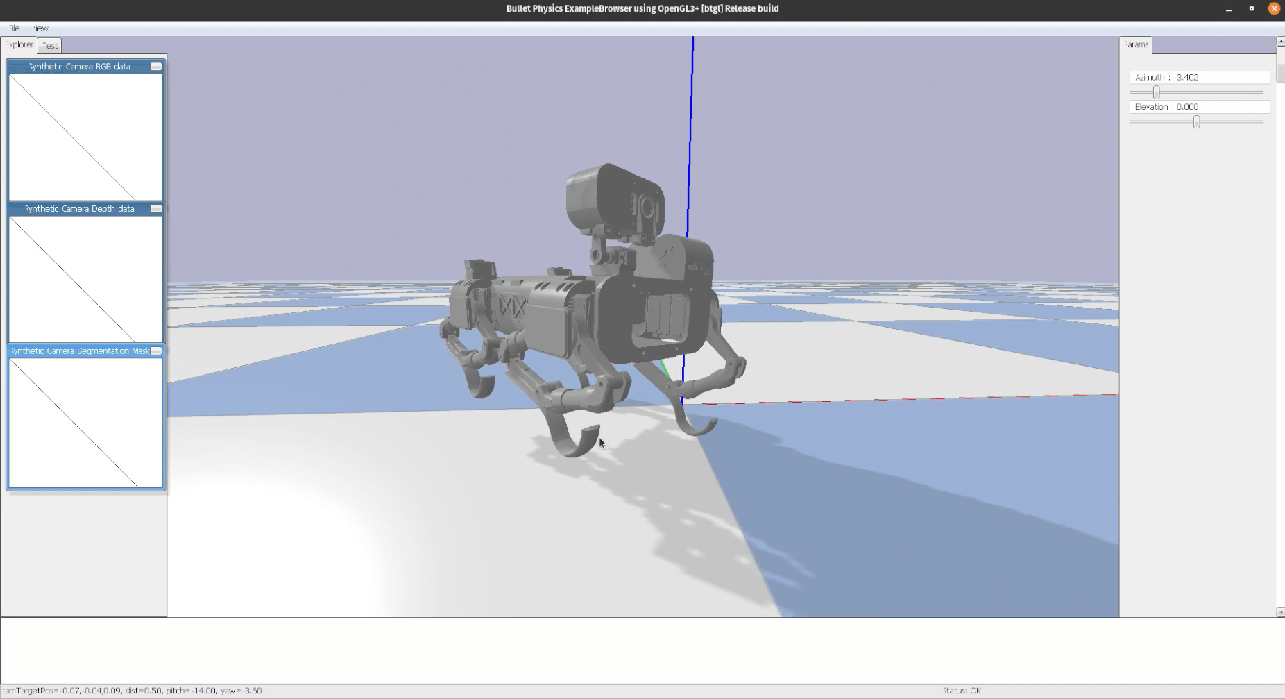
Transitioning from Blender to PyBullet
 Watch: Landing / balancing behaviour
The primary objective this month was to initiate the transition from purely visual and rigid-body modelling in Blender to physics-based simulation in PyBullet. While Blender had served effectively for early kinematic studies and visualisation of Continuity’s geometry, it lacked the dynamic capabilities required to simulate forces, joint torques, and leg-ground interactions in a controlled environment. PyBullet, though less user-friendly from a graphical standpoint, offered a real-time physics engine suitable for iterative testing.
Four legs balancing and exercises

Over the spring, from the beginning of March until the end of May, I focused on balancing Continuity. I tried many different approaches to gain experience and acquire critical thinking in selecting the best one.
- The first one is probably the most complex and common in robot control systems: Proportional Integral Derivative control, or PID. The balancing algorithm was working fine, as can be seen from this video. The PID control is not fine-tuned, but even without doing it, I immediately noticed something I didn't like: motors were weakening approaching the desired position, and losing torque. This behaviour is not normal and it might be caused by an incorrect setup of the power distribution system. Additionally, the servo motors were sometimes rotating to undesired positions, I guess due to overlapping signals (?), causing damage to the mechanical structure of the legs.
Real-time simulations using Blender and Python
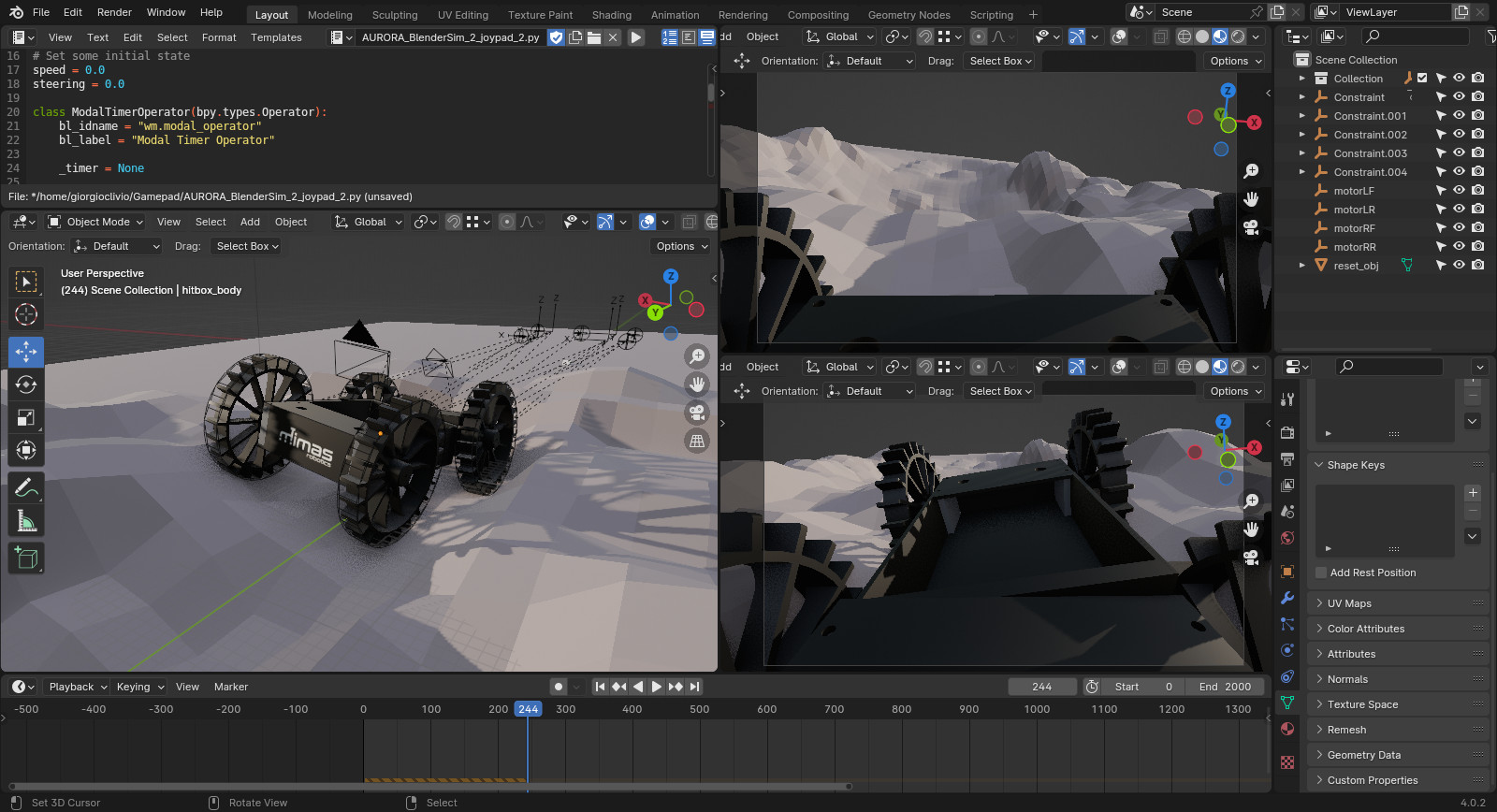 Watch: Aurora Rover: Real-time simulation using Blender and Python
In robotics, real-time simulations are invaluable for testing and refining algorithms, control strategies, and overall system behaviour before deploying solutions to physical robots. I have almost 10 years of experience with Blender, so I decided to use this software, instead of Gazibo or other similar tools. Blender, with its powerful real-time simulation capabilities and powerful render engine, allowed me to interactively control and visualize a robot's movements in a simulated environment allowing me to rapidly iterate on designs, experiment with various scenarios, and fine-tune control parameters in real time. Using a single software for designing the robot, making renderings and animations, but also run physically accurate simulations, not only accelerates the development cycle but also facilitates a seamless transition from simulation to physical implementation.