Transitioning to 6061 Aluminium
 Watch: 1st attempt CNC machining Continuity's parts
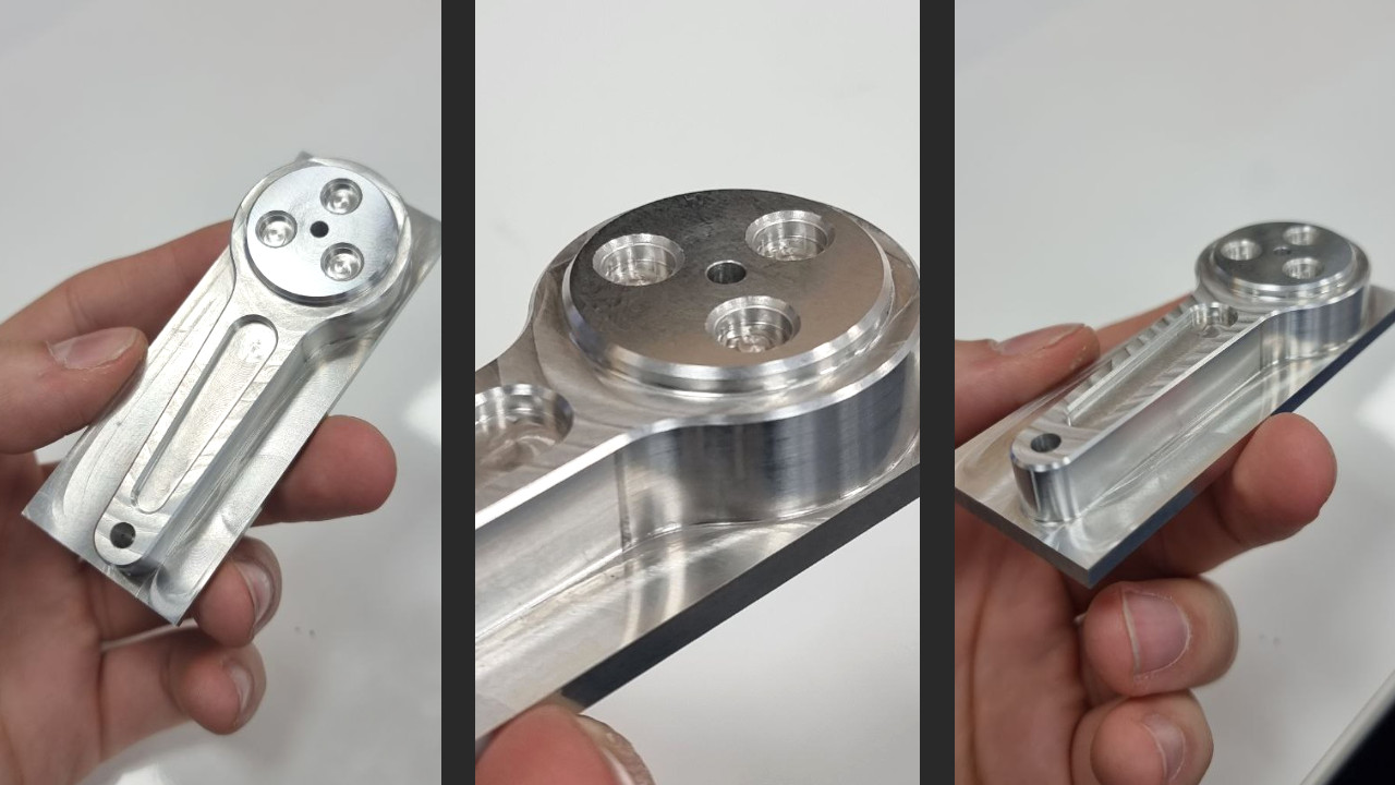
Continuity is currently crafted from 3D-printed PLA plastic, a good material in terms of prototyping flexibility, allowing easy modifications and adjustments. However, as we delve deeper into the mechanical demands, the limitations of PLA become apparent. Achieving structural strength requires high infill or an increase of the external wall count, yet this proves challenging for smaller, intricate parts, where PLA's fragility under load becomes a concern. With the assistance of Edinburgh Napier University's Mechanical Workshop technicians, we are embarking on a transformation. All structural components are undergoing a shift from PLA to robust 6061 Aluminium. This transition necessitates a complete redesign: I used Blender to 3D-model all the pieces, but differently from a 3D printer, CNC machines don't like STL files. To bridge the gap between Blender's polygon-based designs and CNC machines' preference for STEP files, I opted for FreeCad, aligning with my philosophy of using an open-source approach. The photo showcases one of the two top links for Continuity's legs, machined as a test using a CNC machine. The result is good, but not as good as it will be on the actual finished version.
Joypad integration
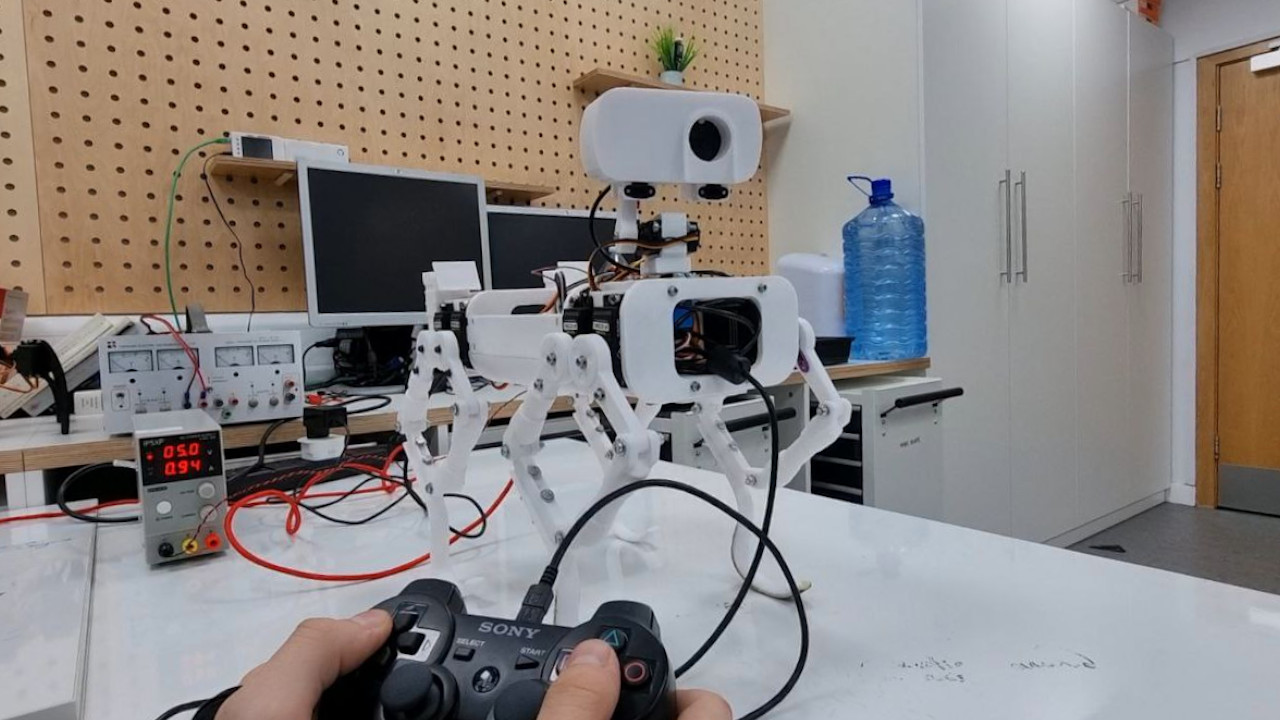
During the last few weeks of testing, I integrated a joypad into Continuity's control methods. This was done to simplify testing on the robot, improving precision and making things a bit more fun when it comes to having a quick demo available to show to people (this happened multiple times, in the past few weeks). I chose to connect a PS3 joypad using the comprehensive features offered by the "Gamepad" GitHub repository. This repository not only simplifies the process but also provides users with multiple joypad configurations, catering to diverse testing needs. In an initial trial, I focused on controlling the Remote Sensing Mast (RSM), a pivotal element of the rover that comes with two degrees of freedom: azimuth rotation and elevation. The RSM serves critical functions such as capturing photos, and panoramic images and facilitating autonomous navigation by aligning with the direction of movement. Subsequent tests focused on legs extension and other general movements, all executed seamlessly through joypad control. While these tests may appear useless given Continuity's ultimate autonomous functionality, being able to control the robot in a user-friendly way is actually extremely important for something that I'm working on aside. I'm trying to develop a simulation framework using Blender, the same open-source software I used for 3D modelling Continuity. Blender is capable of running rigid body simulations and being able to interface them with a Python script might allow me to use it as a real-time simulation tool. More updates will follow on this topic.
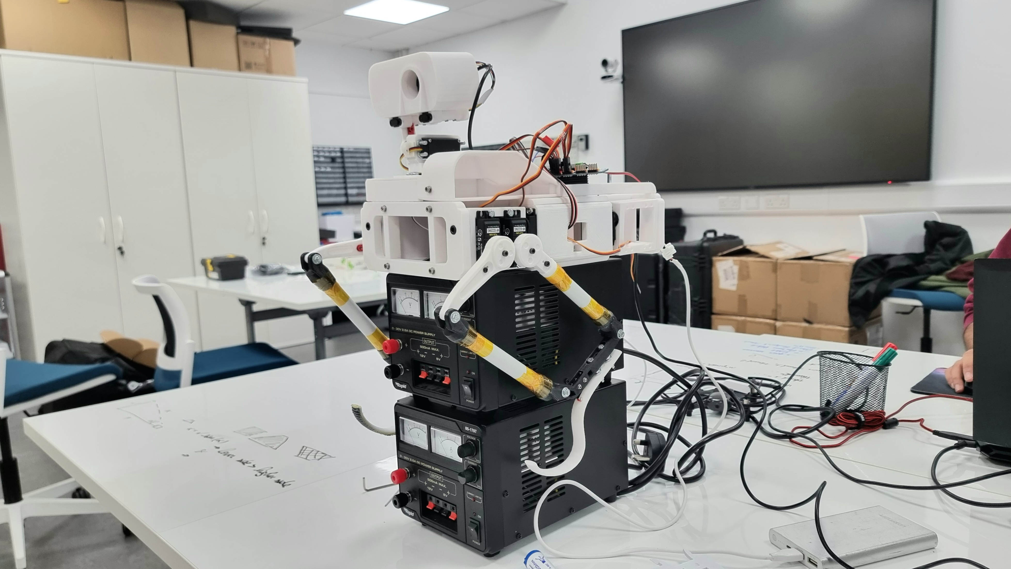
Standing on four legs!
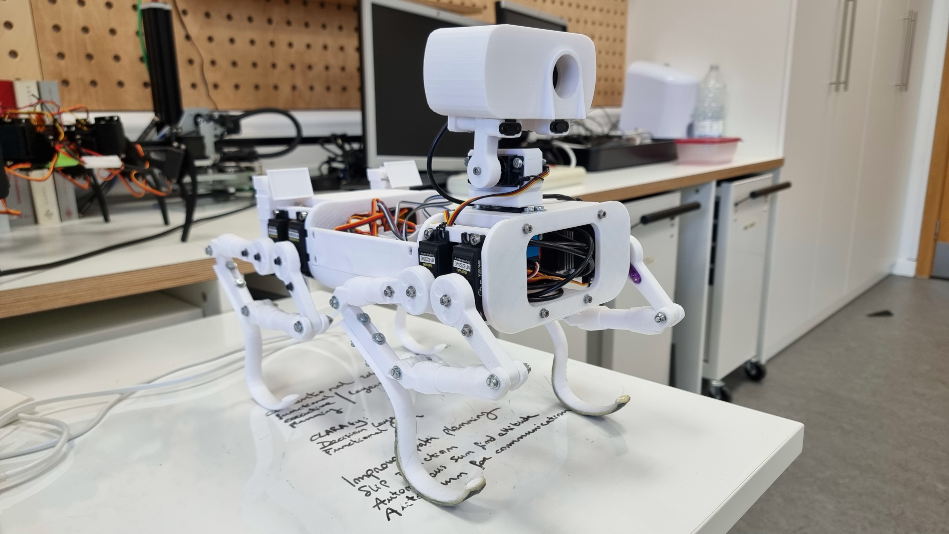
After three months of testing Continuity's front legs only, I'm excited to share that the walking rover has taken a giant leap forward. I've just rolled out an update, bringing the two rear legs into action. This development is a game-changer because now I can dive into real 4-legs-balancing tests, exploring pitch and roll axes movements, along with trying out various walking gaits and manoeuvres. As of now, Continuity is equipped with 8x 25 Kg Servo Motors, each thirsting for 5-7 volts and drawing 1-2 Amps. The entire body is currently made out of 3D-printed PLA, but I've got big plans for the next version: several structural parts of the body will be converted into a sleek carbon fiber structure. The mobility system, aka the legs, is also in for an upgrade, transitioning to a robust aluminium CNC machining.
Rapid Unscheduled Disassembly

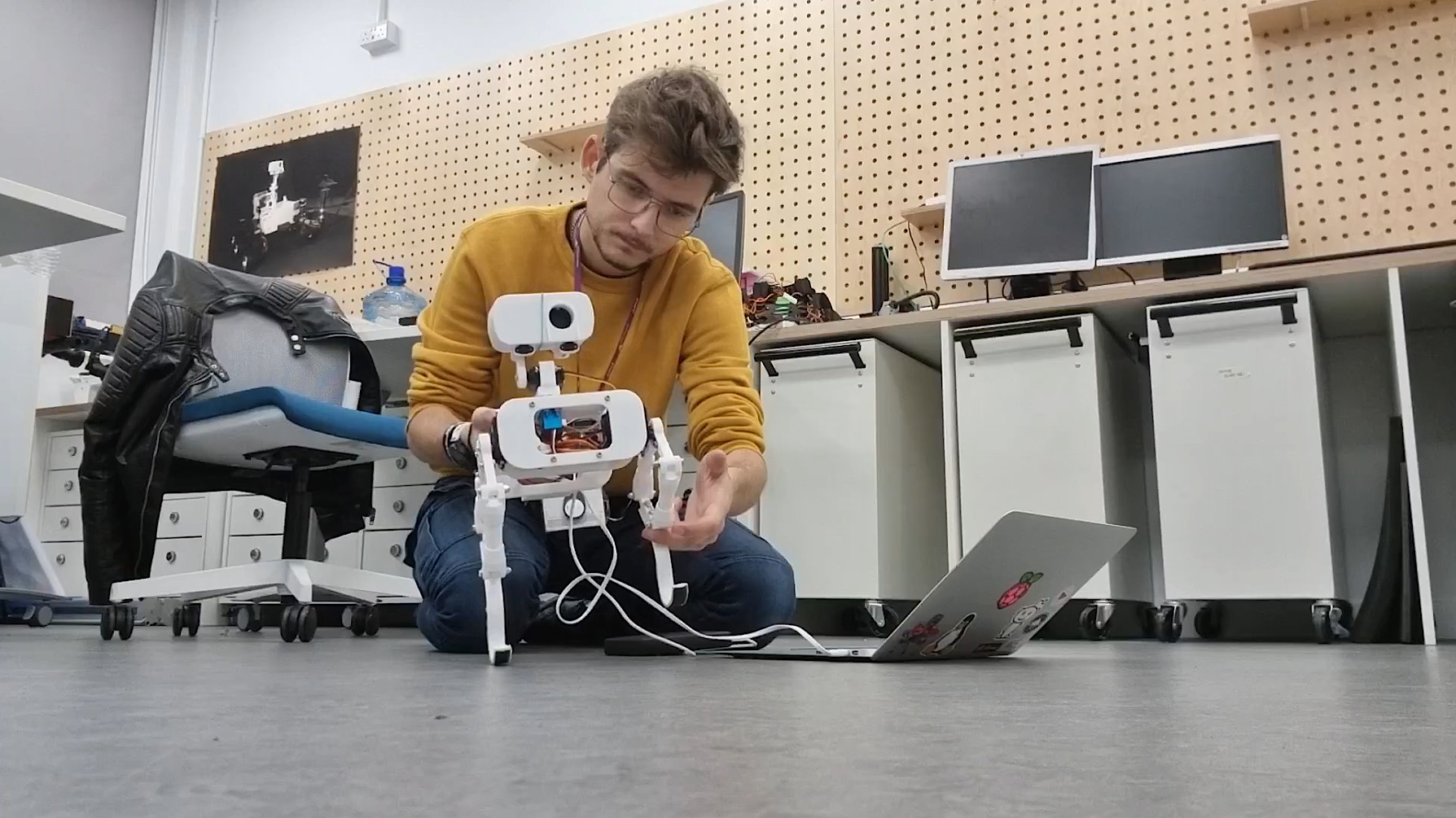
We are not talking about rockets, but apparently, I had to face a Rapid Unscheduled Disassembly of the Mast Tower's head. It doesn’t take a degree in aerospace engineering to know that, ideally, rockets aren’t supposed to blow up. Similarly, a robot is not supposed to break apart during a test. However, this is exactly what happened. During the test, a coding error made one leg go rogue, turning the robot into a bit of a daredevil and resulting in a not-so-graceful tumble from the table. Luckily, the legs and other moving parts survived the crash, but poor Continuity's neck got the worst of it. The elevation mechanism to control the pitch angle of the Imager (the head of the Remote Sensing Mast), is a simple 3D-printed extension of an aluminium servo motor horn. This helps reduce the mechanical complexity, but also makes it much more fragile when the robot has to survive a fall.
Lesson learned: While we love keeping things light and simple, we've got to find that sweet spot between lightweight design and toughness. I am patching up Continuity, adding some extra code safety features, and making sure the robot is ready to handle whatever comes its way. Here's to smoother tests in the future!
Weight Optimization and Two feets roll balancing
 Watch: Two feets roll balancing
In a recent overhaul, Continuity's design underwent a meticulous weight reduction, shedding non-essential components for enhanced efficiency. Then, I started testing balancing on the roll axis, a crucial step towards achieving stability. However, friction-induced squeaking in the plastic joints posed an initial challenge, partially limiting the movements of the legs and causing very annoying noises. I managed to fix the problem using WD-40 lubricant. Balancing is achieved using a simple accelerometer, with future plans to integrate force pressure sensors on Continuity's feet for enhanced feedback. The code I'm using for balancing is not very well refined and occasional failures are acknowledged. But generally speaking, it works well!
Walk Cycle Refinement
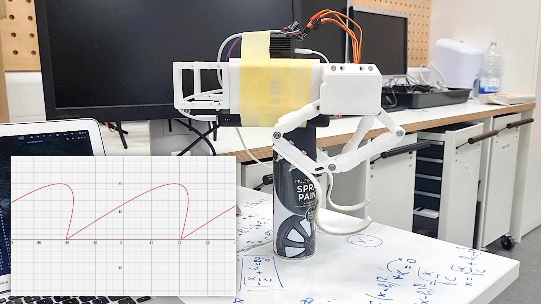
After ensuring a strong enough structure and sufficient current to power the motors, efforts were dedicated to refining the walk cycle of a single leg. Until this point, legs moved along predefined coordinates defined manually, making the movements quite clucky. I decided to avoid inverse kinematics calculations to reduce processing time and resources: this should leave more available memory to the RPi4 for Computer Vision tasks. So, I preferred using forward kinematics, finding a relation between the angles and end effector of the legs. I decided to make the end effector move along a precisely defined curve. This curve comprises two interconnected segments: the upper curve (a), similar (but not) a parabola, and its counterpart below (b), completing a seamless loop.
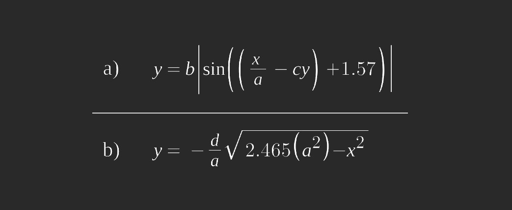 One of the standout features of this approach lies in its adaptability. The parameters of the functions governing the two curves can be fine-tuned, allowing for the creation of diverse step shapes. Whether it's a stable, measured gait or a more dynamic stride, adjusting these parameters provides versatile options. Furthermore, the execution speed of each step is a customizable element, adding another layer of control to the robot's locomotion.
Walk cycle testing and pushups
 Watch: Walk cycle testing and pushups
Between the 6th and the 16th of November, I worked on the control of the legs. The first step was to ensure motors were actually powerful enough to lift the entire body of the rover. Motor strength, however, is not the only parameter affecting this test's success or failure: the length of the leg joints also plays an important role. If the femur or tibia is longer than the other, it can affect the torque required at the joint. Generally, a longer lever arm decreases the torque at the end of the joint. Therefore, if the femur is longer, it may require more torque to move the leg than in a situation where the femur and tibia are more balanced. A combination of the design I was initially using, plus a bottleneck caused by thin cables that were limiting the current draw, was not allowing the robot to lift itself. I use four motors that run between 5 -7 Volts and 1 - 2 Amps powered by a 20000 mAh power bank with an output current of 3 Amps. Nominally, this should not be enough to power four motors. However, good management of the current draw obtained through software allows motors to run anyway. Some suggestions for testing such a configuration are using suitable wires (possibly not jumper wires for connecting the motors to the battery), trying several iterations to find the best leg joint design, recording videos, and taking photos and notes about what you are doing. This helps keep track of your progress, as well as what is not working.
Imager camera and TOF sensor
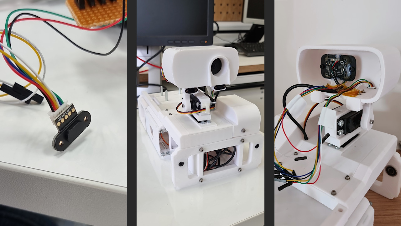
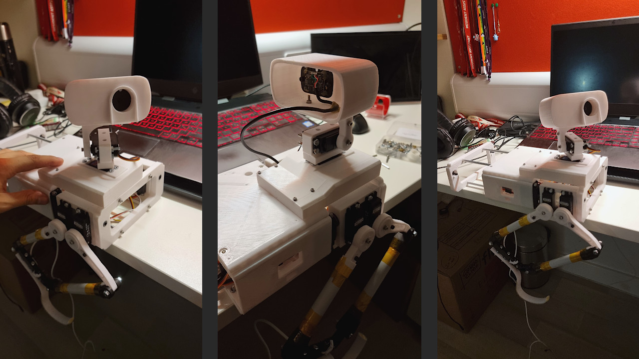
The Imager, that is to say, the top part (or head) of the Mast Tower is the key that justifies the existence of the tower itself: elevating the main rover camera, giving it rotation freedom in all directions. At its current state, Continuity's Imager is equipped with a 1080p camera and a couple of 10120 TOF sensors. A TOF (Time of Flight) is a sensor commonly used on drones due to its extremely low weight. It allows the rover to estimate in real-time the distance between the sensor and an object counting the time light takes to go back and forth from it. Since its precision is not always ensured, I installed a couple of them for redundancy and to get an average of their measurements, obtaining a more reliable value. There is still plenty of space inside the Imager, but this is fine because this will not be its final look, and many parts still need to be improved: for instance, the height of the Mast Tower, which risks being too high compared to the rover centre of mass.
Mast Tower base: 270° servo motor
Five days after assembling the first rough version of the rover body, I came up with a way to reduce the Mast Tower weight and improve, at the same time, its precision. The 3D-printed gearbox has had several backlash problems since the beginning. Additionally, it was heavy and unnecessarily complicated. As discussed, the giant steel bearing used as part of the azimuth rotation mechanism represented a severe issue due to its weight. I decided to try a completely different approach, using a 270-degree servo motor instead. This limits the azimuth rotation, but the precision is significantly increased since the servo uses a potentiometer to rotate to an always-known position. Moreover, there's no need to point the camera towards the side module, located on the LHS of the Mast Tower, since there's nothing to see there.
Rover body first assembly
The rover body is fundamentally made of five parts: the upper and lower deck, the legs assembly, the mast tower and a side module. At the current state of things, the structure is very unbalanced due to the mast tower azimuth motor bearing. However, printing three out of five parts helped me better understand the rover assembly, all available spaces for electronic components, where to pass the cables to power the motors, etc. That said, the mast tower base must be lightened.

The motors I used for the hip joints are a serious weak point of the design since leave a lot of space between pieces and increase the overall weight of the robot. Surely, they are useful in increasing mobility, and adding a degree of freedom, but this might not be a sufficient reason to keep them in the final design.