Reorientation and Bandit-Based Autonomy
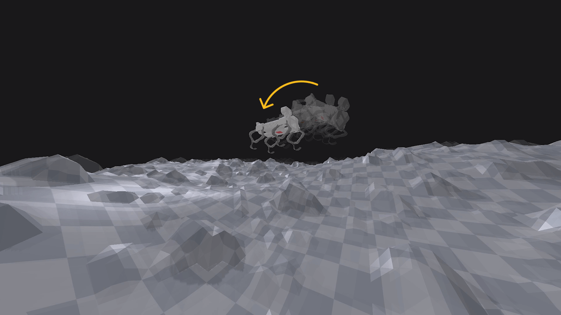 Watch: Self-reorientation attempt using Contextual MAB
During November and December, the project's focus shifted toward a more abstract - but mission-critical - aspect of legged mobility: attitude control and self-reorientation in microgravity conditions. While locomotion on uneven terrains remained a long-term goal, this phase initiated the development of strategies for reorienting a free-floating rigid body using only internal leg motions, without relying on external contacts or torque sources. This involved modelling Continuity as a non-holonomic system in microgravity, where angular momentum is conserved, and reorientation must occur through the redistribution of internal masses - specifically, the four legs. The problem setup mirrors the classical "falling cat" scenario, where a free-floating body must execute sequences of internal movements to rotate in space despite zero net external torque.
Procedural Terrain Generation in PyBullet
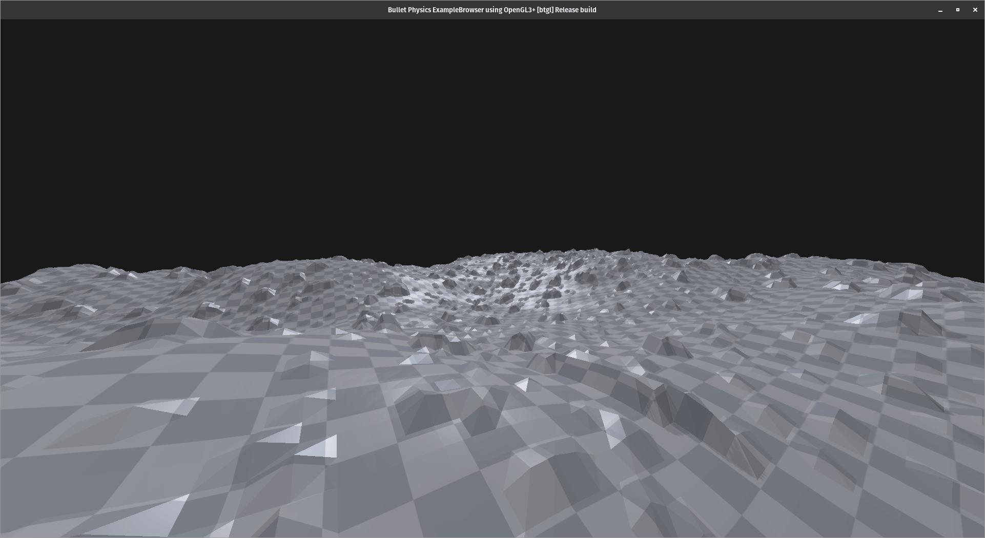
The focus throughout October was on developing a modular terrain generation system within the PyBullet simulation environment. The objective was to build a procedural framework capable of generating diverse terrain types - mountain ranges, valleys, craters, plains, and rocky surfaces - with enough control to vary scale, resolution, and density parameters. Initial prototypes used heightmaps based on Perlin noise and Gaussian distributions to approximate elevation profiles. These methods enabled controllable roughness and large-scale features, with post-processing filters used to either smooth or exaggerate sharpness. To simulate realistic planetary surfaces (e.g. lunar and martian conditions), additional logic was added to introduce crater depressions and scattered rock formations. These could be toggled or adjusted parametrically to study how different environments impact robot behaviour and locomotion strategies. The terrain generator was structured as a standalone Python module, allowing batch generation of terrains with predefined seeds for reproducibility. Each generated terrain could be loaded directly into PyBullet, with optional physics materials for friction, restitution, and compliance tuning.
Transitioning from Blender to PyBullet
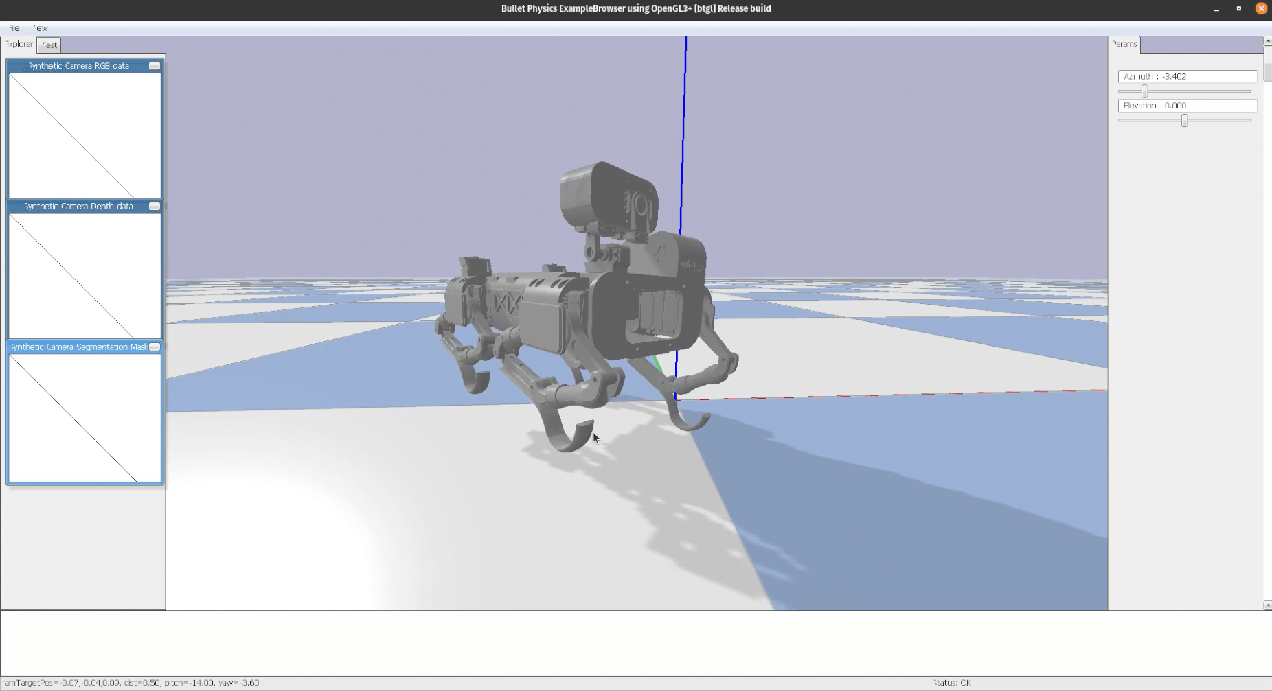 Watch: Landing / balancing behaviour
The primary objective this month was to initiate the transition from purely visual and rigid-body modelling in Blender to physics-based simulation in PyBullet. While Blender had served effectively for early kinematic studies and visualisation of Continuity’s geometry, it lacked the dynamic capabilities required to simulate forces, joint torques, and leg-ground interactions in a controlled environment. PyBullet, though less user-friendly from a graphical standpoint, offered a real-time physics engine suitable for iterative testing.
Four legs balancing and exercises

Over the spring, from the beginning of March until the end of May, I focused on balancing Continuity. I tried many different approaches to gain experience and acquire critical thinking in selecting the best one.
- The first one is probably the most complex and common in robot control systems: Proportional Integral Derivative control, or PID. The balancing algorithm was working fine, as can be seen from this video. The PID control is not fine-tuned, but even without doing it, I immediately noticed something I didn't like: motors were weakening approaching the desired position, and losing torque. This behaviour is not normal and it might be caused by an incorrect setup of the power distribution system. Additionally, the servo motors were sometimes rotating to undesired positions, I guess due to overlapping signals (?), causing damage to the mechanical structure of the legs.
Real-time simulations using Blender and Python
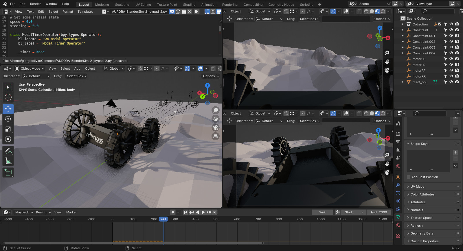 Watch: Aurora Rover: Real-time simulation using Blender and Python
In robotics, real-time simulations are invaluable for testing and refining algorithms, control strategies, and overall system behaviour before deploying solutions to physical robots. I have almost 10 years of experience with Blender, so I decided to use this software, instead of Gazibo or other similar tools. Blender, with its powerful real-time simulation capabilities and powerful render engine, allowed me to interactively control and visualize a robot's movements in a simulated environment allowing me to rapidly iterate on designs, experiment with various scenarios, and fine-tune control parameters in real time. Using a single software for designing the robot, making renderings and animations, but also run physically accurate simulations, not only accelerates the development cycle but also facilitates a seamless transition from simulation to physical implementation.
Transitioning to 6061 Aluminium
 Watch: 1st attempt CNC machining Continuity's parts
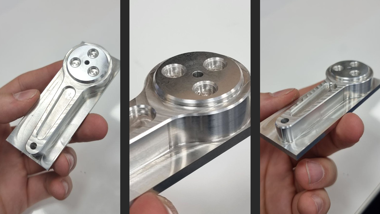
Continuity is currently crafted from 3D-printed PLA plastic, a good material in terms of prototyping flexibility, allowing easy modifications and adjustments. However, as we delve deeper into the mechanical demands, the limitations of PLA become apparent. Achieving structural strength requires high infill or an increase of the external wall count, yet this proves challenging for smaller, intricate parts, where PLA's fragility under load becomes a concern. With the assistance of Edinburgh Napier University's Mechanical Workshop technicians, we are embarking on a transformation. All structural components are undergoing a shift from PLA to robust 6061 Aluminium. This transition necessitates a complete redesign: I used Blender to 3D-model all the pieces, but differently from a 3D printer, CNC machines don't like STL files. To bridge the gap between Blender's polygon-based designs and CNC machines' preference for STEP files, I opted for FreeCad, aligning with my philosophy of using an open-source approach. The photo showcases one of the two top links for Continuity's legs, machined as a test using a CNC machine. The result is good, but not as good as it will be on the actual finished version.
Joypad integration
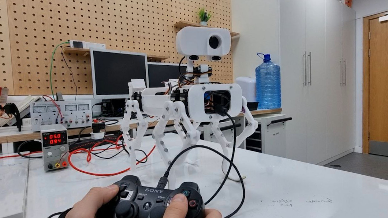
During the last few weeks of testing, I integrated a joypad into Continuity's control methods. This was done to simplify testing on the robot, improving precision and making things a bit more fun when it comes to having a quick demo available to show to people (this happened multiple times, in the past few weeks). I chose to connect a PS3 joypad using the comprehensive features offered by the "Gamepad" GitHub repository. This repository not only simplifies the process but also provides users with multiple joypad configurations, catering to diverse testing needs. In an initial trial, I focused on controlling the Remote Sensing Mast (RSM), a pivotal element of the rover that comes with two degrees of freedom: azimuth rotation and elevation. The RSM serves critical functions such as capturing photos, and panoramic images and facilitating autonomous navigation by aligning with the direction of movement. Subsequent tests focused on legs extension and other general movements, all executed seamlessly through joypad control. While these tests may appear useless given Continuity's ultimate autonomous functionality, being able to control the robot in a user-friendly way is actually extremely important for something that I'm working on aside. I'm trying to develop a simulation framework using Blender, the same open-source software I used for 3D modelling Continuity. Blender is capable of running rigid body simulations and being able to interface them with a Python script might allow me to use it as a real-time simulation tool. More updates will follow on this topic.
Standing on four legs!
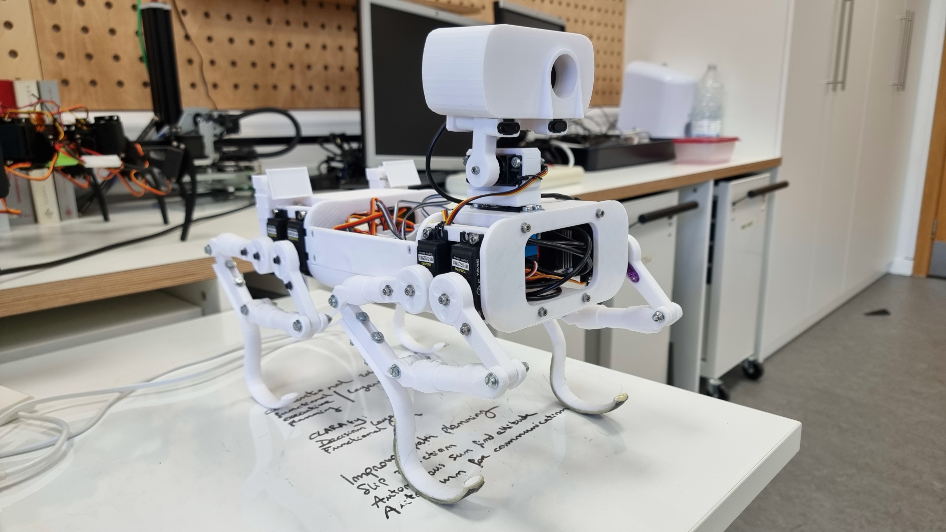
After three months of testing Continuity's front legs only, I'm excited to share that the walking rover has taken a giant leap forward. I've just rolled out an update, bringing the two rear legs into action. This development is a game-changer because now I can dive into real 4-legs-balancing tests, exploring pitch and roll axes movements, along with trying out various walking gaits and manoeuvres. As of now, Continuity is equipped with 8x 25 Kg Servo Motors, each thirsting for 5-7 volts and drawing 1-2 Amps. The entire body is currently made out of 3D-printed PLA, but I've got big plans for the next version: several structural parts of the body will be converted into a sleek carbon fiber structure. The mobility system, aka the legs, is also in for an upgrade, transitioning to a robust aluminium CNC machining.