Weight Optimization and Two feets roll balancing
 Watch: Two feets roll balancing
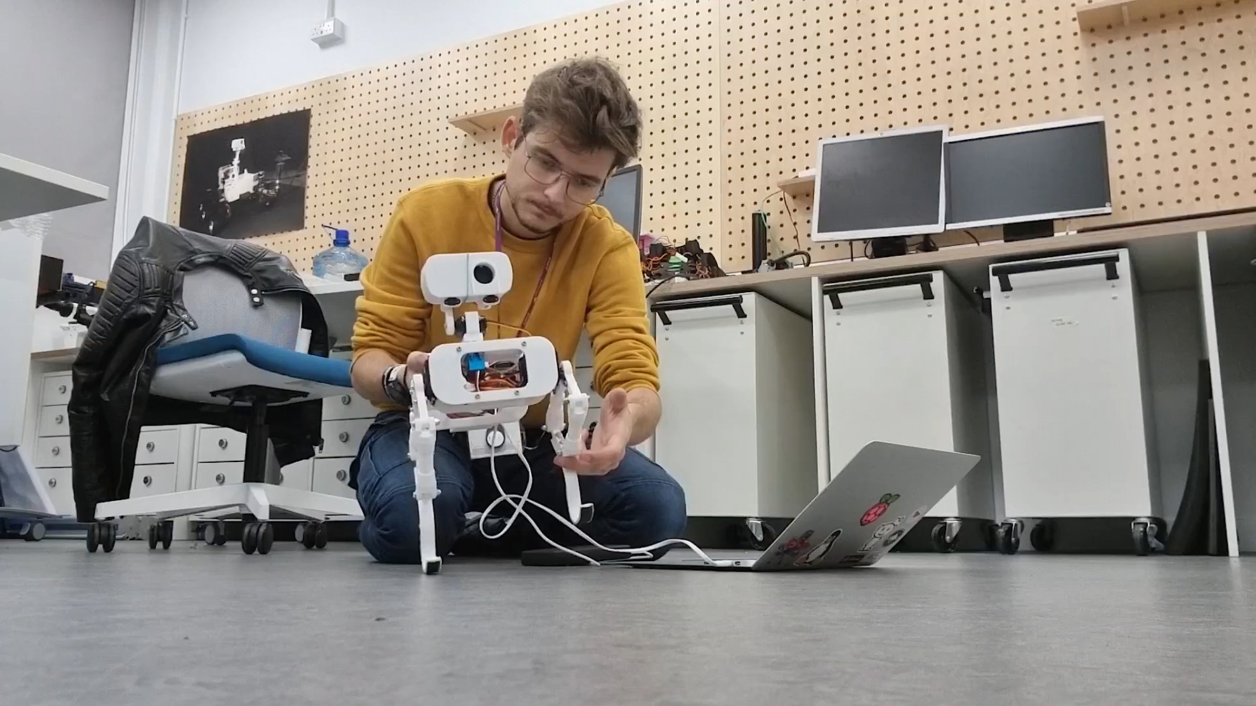
In a recent overhaul, Continuity's design underwent a meticulous weight reduction, shedding non-essential components for enhanced efficiency. Then, I started testing balancing on the roll axis, a crucial step towards achieving stability. However, friction-induced squeaking in the plastic joints posed an initial challenge, partially limiting the movements of the legs and causing very annoying noises. I managed to fix the problem using WD-40 lubricant. Balancing is achieved using a simple accelerometer, with future plans to integrate force pressure sensors on Continuity's feet for enhanced feedback. The code I'm using for balancing is not very well refined and occasional failures are acknowledged. But generally speaking, it works well!
Walk Cycle Refinement
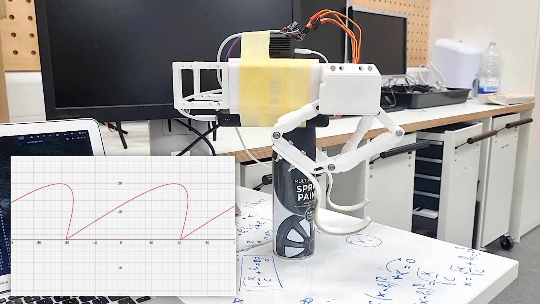
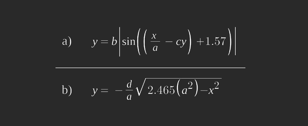
After ensuring a strong enough structure and sufficient current to power the motors, efforts were dedicated to refining the walk cycle of a single leg. Until this point, legs moved along predefined coordinates defined manually, making the movements quite clucky. I decided to avoid inverse kinematics calculations to reduce processing time and resources: this should leave more available memory to the RPi4 for Computer Vision tasks. So, I preferred using forward kinematics, finding a relation between the angles and end effector of the legs. I decided to make the end effector move along a precisely defined curve. This curve comprises two interconnected segments: the upper curve (a), similar (but not) a parabola, and its counterpart below (b), completing a seamless loop.
 One of the standout features of this approach lies in its adaptability. The parameters of the functions governing the two curves can be fine-tuned, allowing for the creation of diverse step shapes. Whether it's a stable, measured gait or a more dynamic stride, adjusting these parameters provides versatile options. Furthermore, the execution speed of each step is a customizable element, adding another layer of control to the robot's locomotion.
Walk cycle testing and pushups
 Watch: Walk cycle testing and pushups
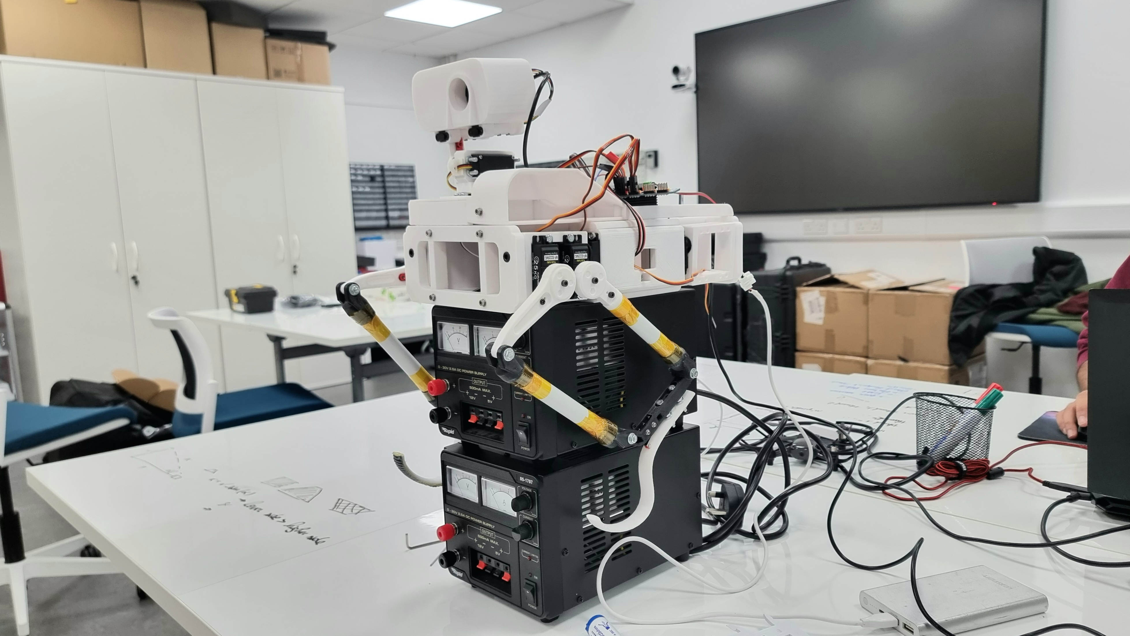
Between the 6th and the 16th of November, I worked on the control of the legs. The first step was to ensure motors were actually powerful enough to lift the entire body of the rover. Motor strength, however, is not the only parameter affecting this test's success or failure: the length of the leg joints also plays an important role. If the femur or tibia is longer than the other, it can affect the torque required at the joint. Generally, a longer lever arm decreases the torque at the end of the joint. Therefore, if the femur is longer, it may require more torque to move the leg than in a situation where the femur and tibia are more balanced. A combination of the design I was initially using, plus a bottleneck caused by thin cables that were limiting the current draw, was not allowing the robot to lift itself. I use four motors that run between 5 -7 Volts and 1 - 2 Amps powered by a 20000 mAh power bank with an output current of 3 Amps. Nominally, this should not be enough to power four motors. However, good management of the current draw obtained through software allows motors to run anyway. Some suggestions for testing such a configuration are using suitable wires (possibly not jumper wires for connecting the motors to the battery), trying several iterations to find the best leg joint design, recording videos, and taking photos and notes about what you are doing. This helps keep track of your progress, as well as what is not working.