Thank you!
Designing, building and testing Continuity requires a lot of effort and I invite you to be a part of it! Your support can fuels the Research, allowing me to test new technologies and materials, enabling exploration of new horizons. Every donation, no matter the size, is really appreciated. By contributing, you're not just funding Research; you're becoming a cherished member of a community, making this project come true.
ALL FUNDS raised are used for this Research. I really appreciate any help you can provide 🙏🏻 . https://gofund.me/55b980c0
Quick facts!
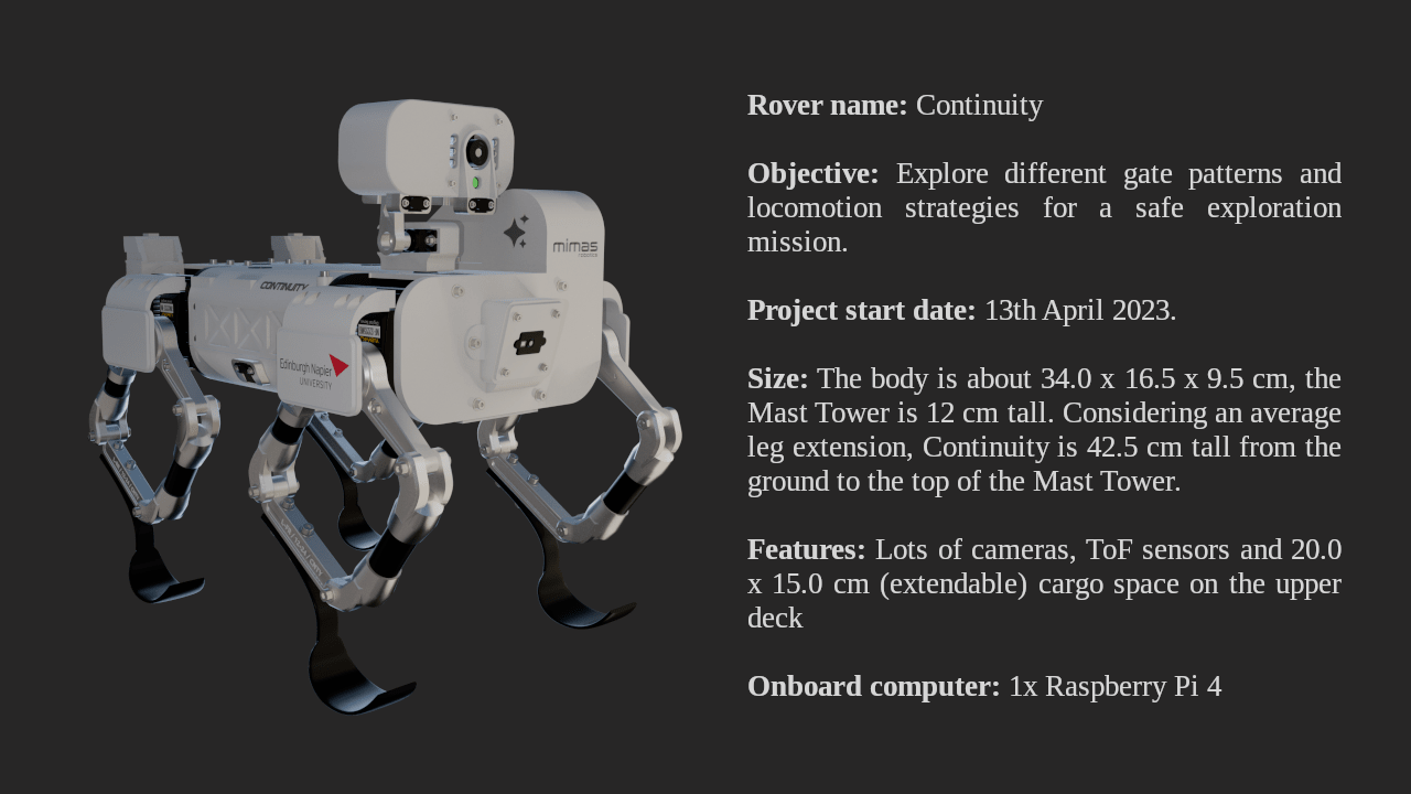 Continuity is designed to be as compact as possible, taking inspiration from already-existing quadruped robots, and integrating specific features of planetary rovers.
Using a small and relatively cheap robot for planetary exploration would guarantee access to inaccessible areas, like rocky slopes, craters and caves. Ideally, if a group of "Continuity" rovers cooperate in a multi-robot mission, it would be possible to sacrifice one of them for a hazardous mission, while keeping the others safe.
Continuity is designed to be as compact as possible, taking inspiration from already-existing quadruped robots, and integrating specific features of planetary rovers.
Using a small and relatively cheap robot for planetary exploration would guarantee access to inaccessible areas, like rocky slopes, craters and caves. Ideally, if a group of "Continuity" rovers cooperate in a multi-robot mission, it would be possible to sacrifice one of them for a hazardous mission, while keeping the others safe.
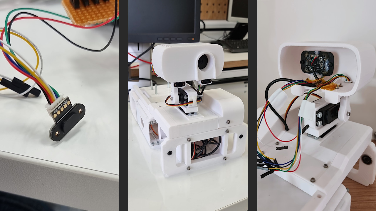
Imager camera and TOF sensor
The Imager, that is to say, the top part (or head) of the Mast Tower is the key that justifies the existence of the tower itself: elevating the main rover camera, giving it rotation freedom in all directions. At its current state, Continuity's Imager is equipped with a 1080p camera and a couple of 10120 TOF sensors. A TOF (Time of Flight) is a sensor commonly used on drones due to its extremely low weight. It allows the rover to estimate in real-time the distance between the sensor and an object counting the time light takes to go back and forth from it. Since its precision is not always ensured, I installed a couple of them for redundancy and to get an average of their measurements, obtaining a more reliable value. There is still plenty of space inside the Imager, but this is fine because this will not be its final look, and many parts still need to be improved: for instance, the height of the Mast Tower, which risks being too high compared to the rover centre of mass.
Mast Tower base: 270° servo motor
Five days after assembling the first rough version of the rover body, I came up with a way to reduce the Mast Tower weight and improve, at the same time, its precision. The 3D-printed gearbox has had several backlash problems since the beginning. Additionally, it was heavy and unnecessarily complicated. As discussed, the giant steel bearing used as part of the azimuth rotation mechanism represented a severe issue due to its weight. I decided to try a completely different approach, using a 270-degree servo motor instead. This limits the azimuth rotation, but the precision is significantly increased since the servo uses a potentiometer to rotate to an always-known position. Moreover, there's no need to point the camera towards the side module, located on the LHS of the Mast Tower, since there's nothing to see there.
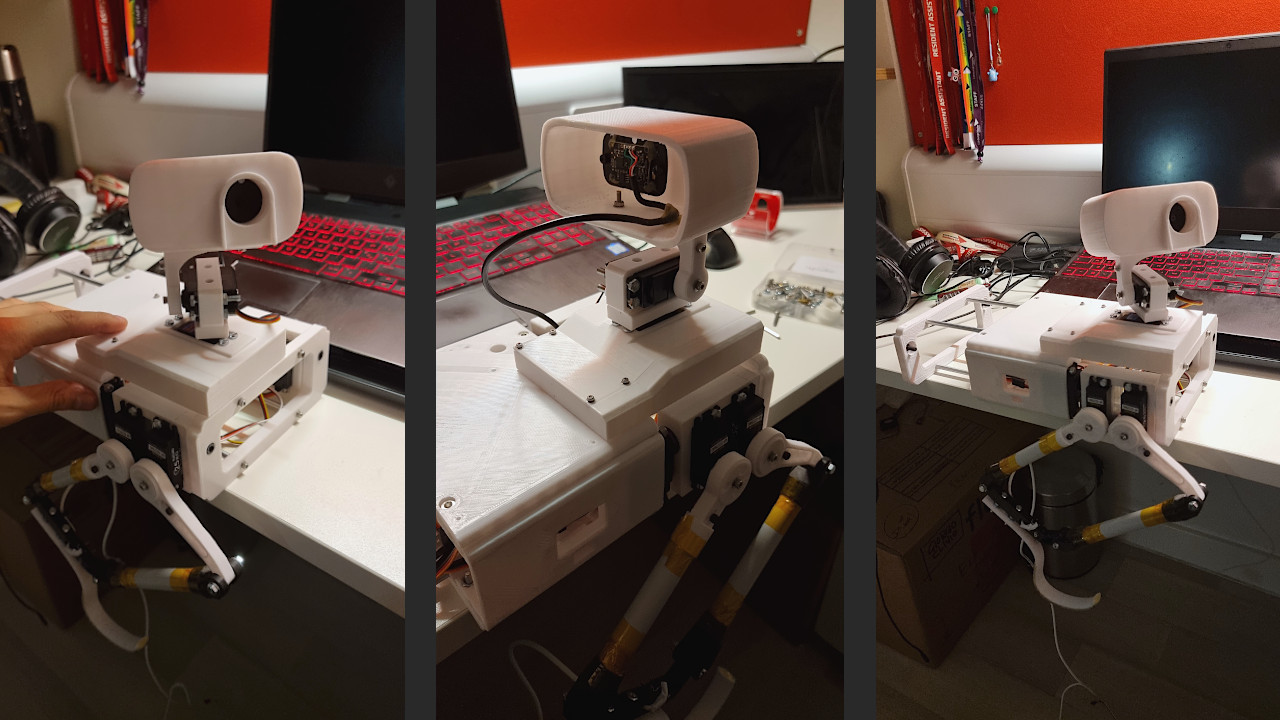
Rover body first assembly
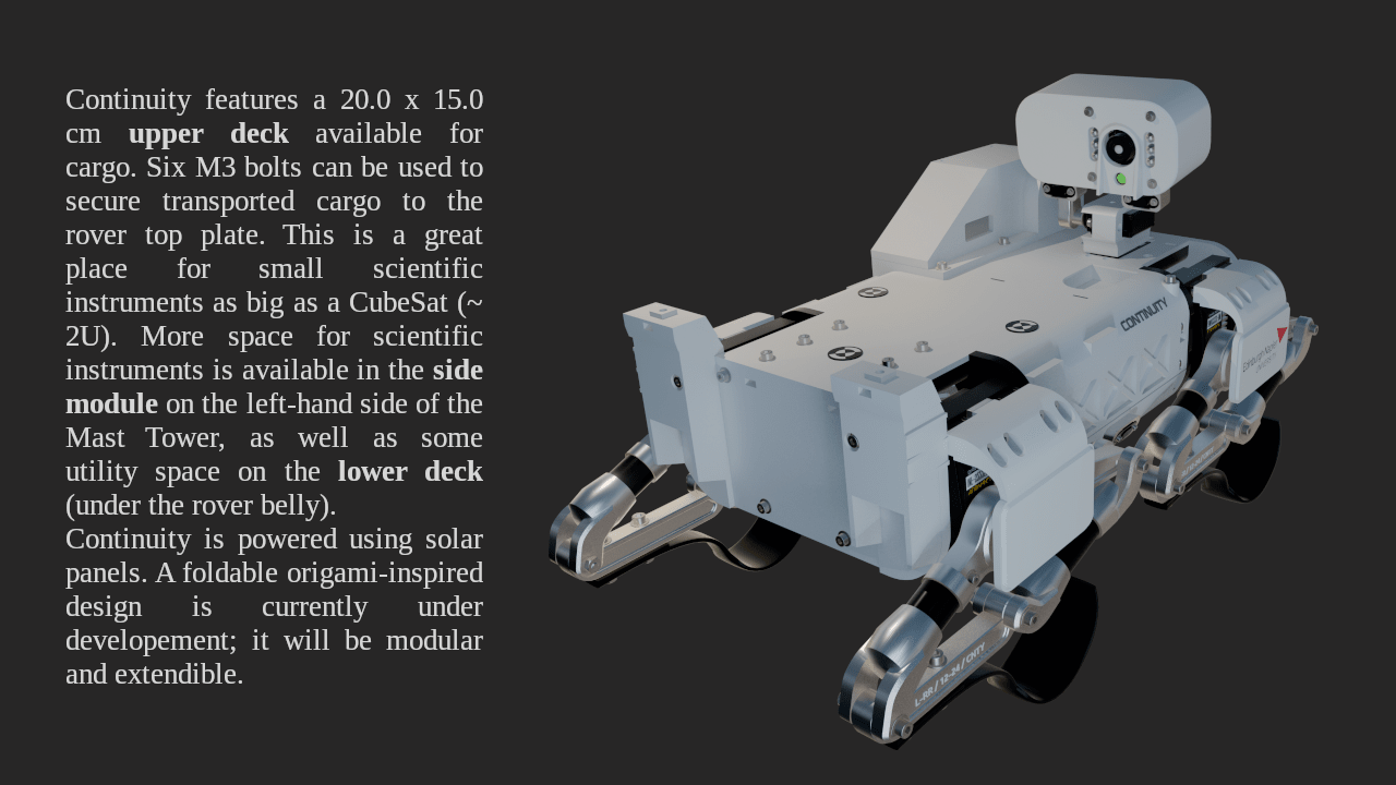
The rover body is fundamentally made of five parts: the upper and lower deck, the legs assembly, the mast tower and a side module. At the current state of things, the structure is very unbalanced due to the mast tower azimuth motor bearing. However, printing three out of five parts helped me better understand the rover assembly, all available spaces for electronic components, where to pass the cables to power the motors, etc. That said, the mast tower base must be lightened.

The motors I used for the hip joints are a serious weak point of the design since leave a lot of space between pieces and increase the overall weight of the robot. Surely, they are useful in increasing mobility, and adding a degree of freedom, but this might not be a sufficient reason to keep them in the final design.