Welcome! This is the logbook for "Continuity" project.
Hi, I'm Giorgio, a student at Edinburgh Napier University. In July 2023 I got my Bachelor's Degree in Mechanical Engineering, and now I'm carrying out a PhD Research focused on a Planetary Robotics project. The Research aims to "explore different gait patterns and locomotion strategies to identify the most significant parameters affecting an optimal gait selection". The Research is conducted on a specially designed walking robot, designed from scratch and Open Source. The title project is "Legged excursion on unstructured surfaces", and the robot/rover name is Continuity!
This website is a roadmap blog / logbook to keep interested people updated on every step of the Research. For practical reasons, the blog writing format is unformal, making it more accessible and understandable for readers, and easily updatable for me.
- University email: 40445471@live.napier.ac.uk
- Personal email: giorgio@clivio.net
- LinkedIn: Giorgio Clivio
All funds raised are used for this Research. I really appreciate any help you can provide. https://gofund.me/55b980c0
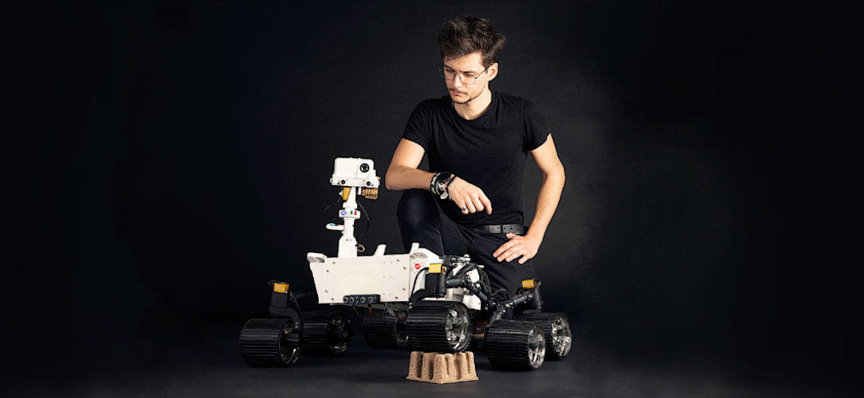 This is me with Mimas Rover, a Mars Rover replica that I built as Honours Project at ENU.
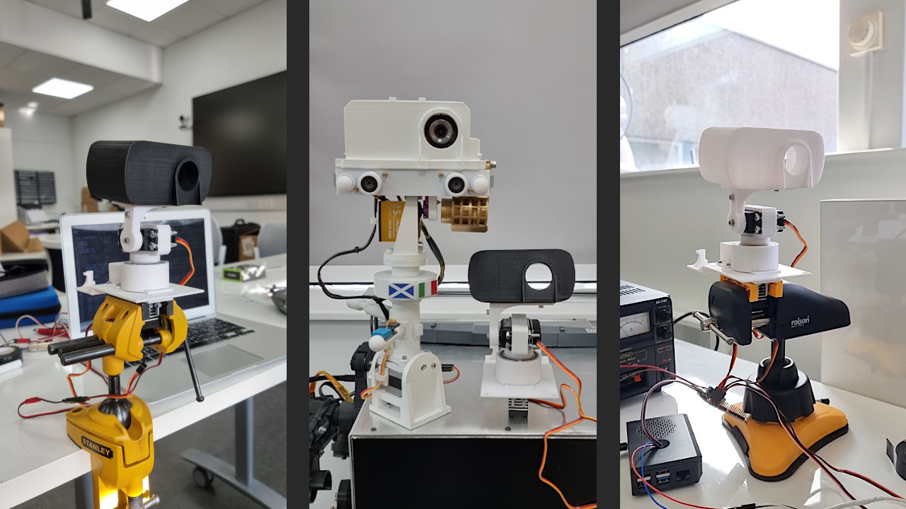
Continuity and Mimas's mast tower comparison
After a week of testing, the mast tower v.1 was ready! I tested two versions of the head (with a slight variation in weight - the final version is the white one) and verified the precision of the 3D-printed gearbox: despite a backlash of < 0.5 cm, it performs smoothly and is visually precise. This is something that must be improved in v.2, possibly reducing the backlash to < 0.2 cm or lower. I also compared the mast tower of Continuity with Mimas' one: the difference is really impressive, but despite being shorter, Continuity's mast tower is much more capable! It will be equipped with a higher resolution camera (compared to Mimas' camera), laser distance sensors and other instruments!
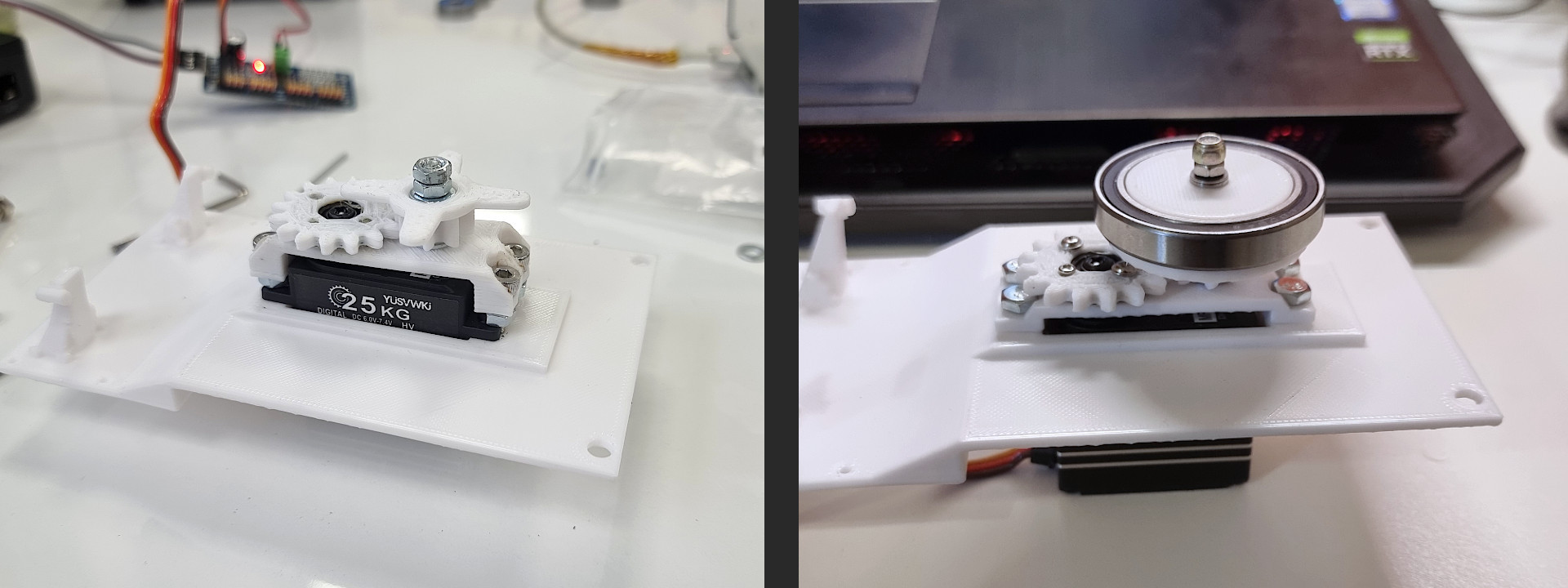
Mast Tower base: 3D printed multiplier gearbox
The mast tower is a crucial element of Continuity: it is a tower-shaped component that elevates key camera systems and sensors, giving the rover a human-scale perspective on its environment. Because I decided to use only servo motors, where possible, I had to find a way to increase the rotation range of the motor. The servos I'm using are 25 Kg full-metal motors with a rotation range of 180°, meaning that they cannot be used directly for the azimuth rotation (along the z-axis). I decided to 3D print a 1:2 (2x) multiplier gearbox. You can see it in the LHS photo below. The design is probably not the best because the gears are very thick and not space-saving. I still decided to give them a chance, so I designed a holder for a bearing and an enclosure to keep everything tight and reduce vibrations. Now, when I rotate the servo by 180°, I get a 360° rotation. There is still an evident issue: 3D-printed gears are not 100% accurate, and backlash is not something I can ignore.
Keep it light and simple!
It might sound obvious, but keeping the design lightweight and simple, without unnecessary mass additions and frills can significantly reduce the production time and limit failures. Four months after the design of the first concept, I realised several parts were unnecessary, making the overall structure bulky and heavy. The figure below shows how the servo motor holder for one of the legs has been simplified, reducing the mass as much as possible, but still keeping it strong. 33g

On the LHS of the photo, the black piece shows a vertical part with five holes designed to hold a metal flange. The old design was 33g heavy, the new design shows an improvement of 51.5%, weighting just 16g.
Front linkage update
Until the day of this post writing, the front and rear upper linkages of the leg were connected to the motors using aluminium flanges. Generally speaking, this component is great but performs poorly if an overhung stress is applied to the motor shaft, causing vibrations that tend to increase after intense testing of the leg. To (hopefully) fix the problem, I changed the design, substituting the flange with an aluminium bracket that can be secured to the motor shaft using small set screws. Additionally, this design increases the contact area between metal and plastic, improving the force distribution.

This configuration has been tested by running the same tests performed with the previous design. Results show that not only the vibrations are reduced (as well as the chance that screws get unscrewed due to vibrations), but also improve the stability of the leg when it was tested sideways and upside down.