Rapid Unscheduled Disassembly

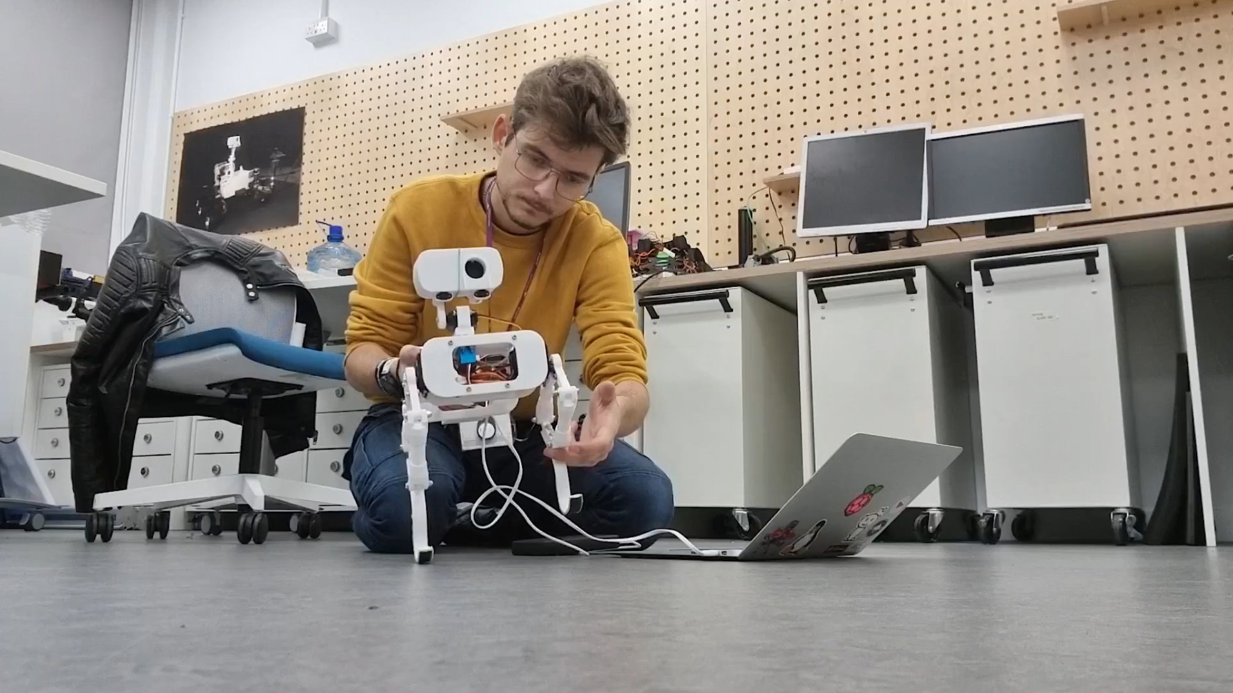
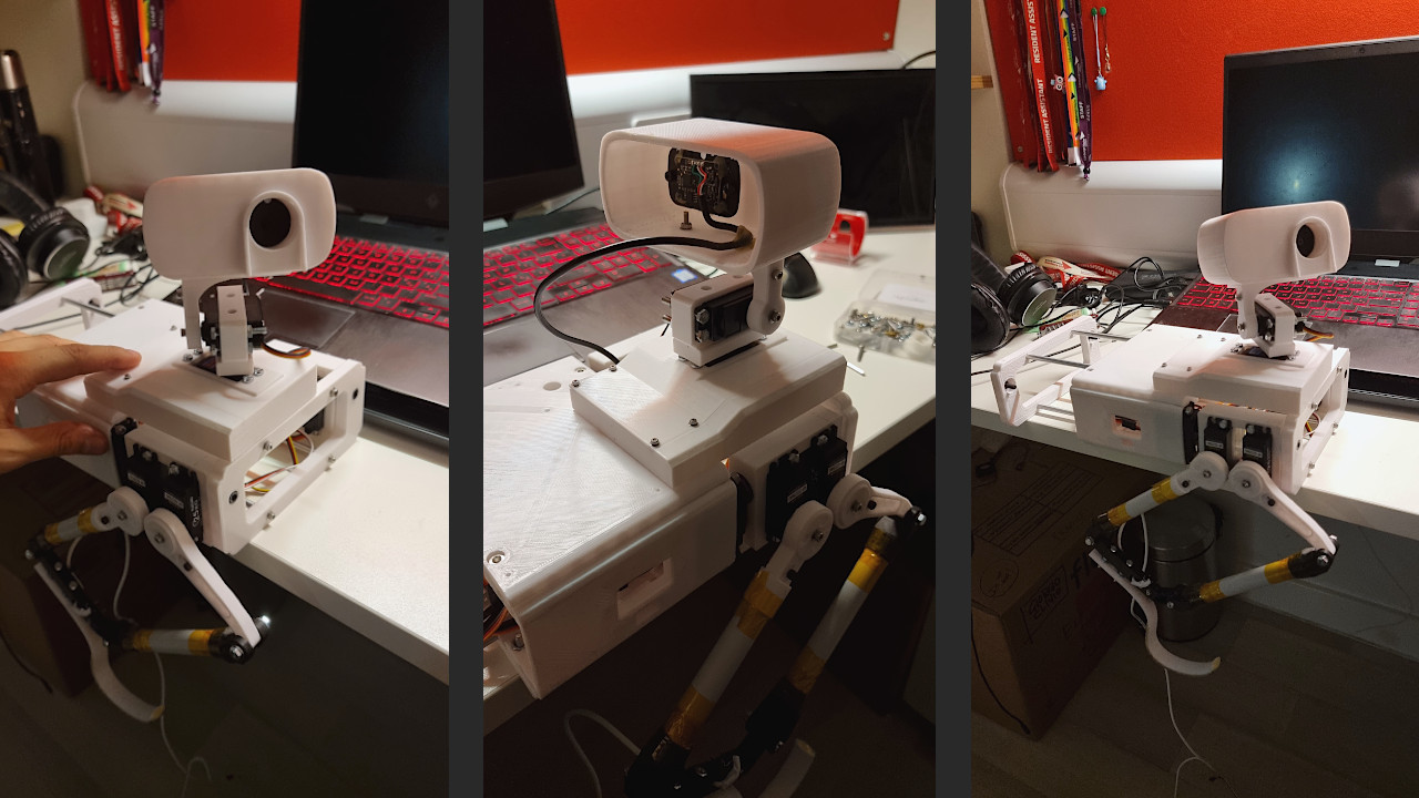
We are not talking about rockets, but apparently, I had to face a Rapid Unscheduled Disassembly of the Mast Tower's head. It doesn’t take a degree in aerospace engineering to know that, ideally, rockets aren’t supposed to blow up. Similarly, a robot is not supposed to break apart during a test. However, this is exactly what happened. During the test, a coding error made one leg go rogue, turning the robot into a bit of a daredevil and resulting in a not-so-graceful tumble from the table. Luckily, the legs and other moving parts survived the crash, but poor Continuity's neck got the worst of it. The elevation mechanism to control the pitch angle of the Imager (the head of the Remote Sensing Mast), is a simple 3D-printed extension of an aluminium servo motor horn. This helps reduce the mechanical complexity, but also makes it much more fragile when the robot has to survive a fall.
Lesson learned: While we love keeping things light and simple, we've got to find that sweet spot between lightweight design and toughness. I am patching up Continuity, adding some extra code safety features, and making sure the robot is ready to handle whatever comes its way. Here's to smoother tests in the future!
Weight Optimization and Two feets roll balancing
 Watch: Two feets roll balancing
In a recent overhaul, Continuity's design underwent a meticulous weight reduction, shedding non-essential components for enhanced efficiency. Then, I started testing balancing on the roll axis, a crucial step towards achieving stability. However, friction-induced squeaking in the plastic joints posed an initial challenge, partially limiting the movements of the legs and causing very annoying noises. I managed to fix the problem using WD-40 lubricant. Balancing is achieved using a simple accelerometer, with future plans to integrate force pressure sensors on Continuity's feet for enhanced feedback. The code I'm using for balancing is not very well refined and occasional failures are acknowledged. But generally speaking, it works well!
Walk Cycle Refinement
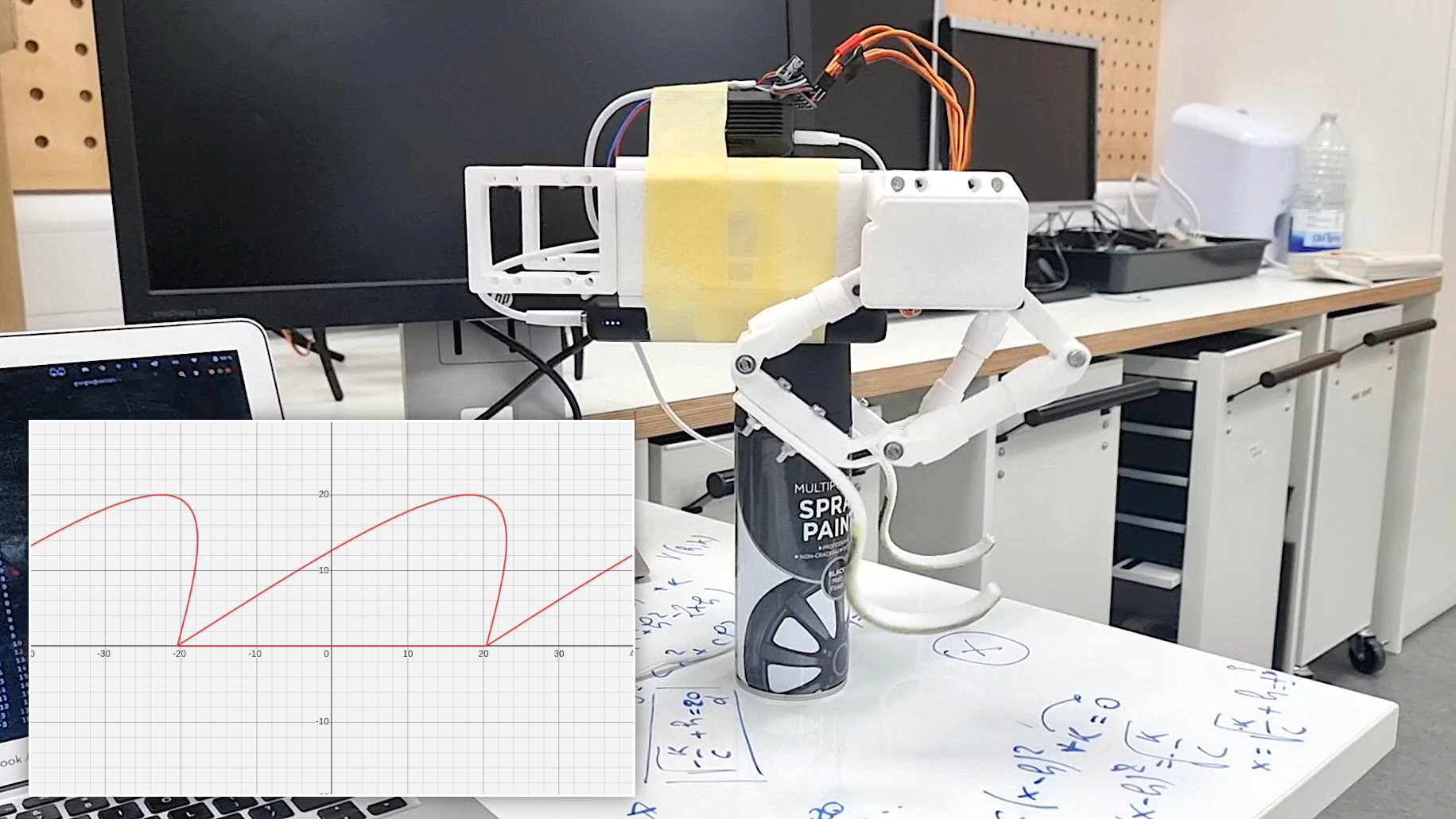
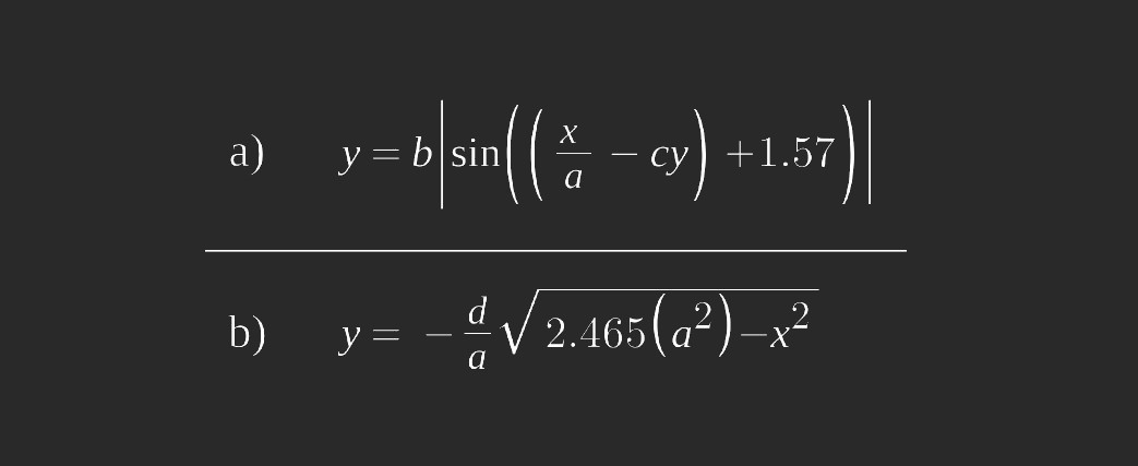
After ensuring a strong enough structure and sufficient current to power the motors, efforts were dedicated to refining the walk cycle of a single leg. Until this point, legs moved along predefined coordinates defined manually, making the movements quite clucky. I decided to avoid inverse kinematics calculations to reduce processing time and resources: this should leave more available memory to the RPi4 for Computer Vision tasks. So, I preferred using forward kinematics, finding a relation between the angles and end effector of the legs. I decided to make the end effector move along a precisely defined curve. This curve comprises two interconnected segments: the upper curve (a), similar (but not) a parabola, and its counterpart below (b), completing a seamless loop.
 One of the standout features of this approach lies in its adaptability. The parameters of the functions governing the two curves can be fine-tuned, allowing for the creation of diverse step shapes. Whether it's a stable, measured gait or a more dynamic stride, adjusting these parameters provides versatile options. Furthermore, the execution speed of each step is a customizable element, adding another layer of control to the robot's locomotion.
Walk cycle testing and pushups
 Watch: Walk cycle testing and pushups
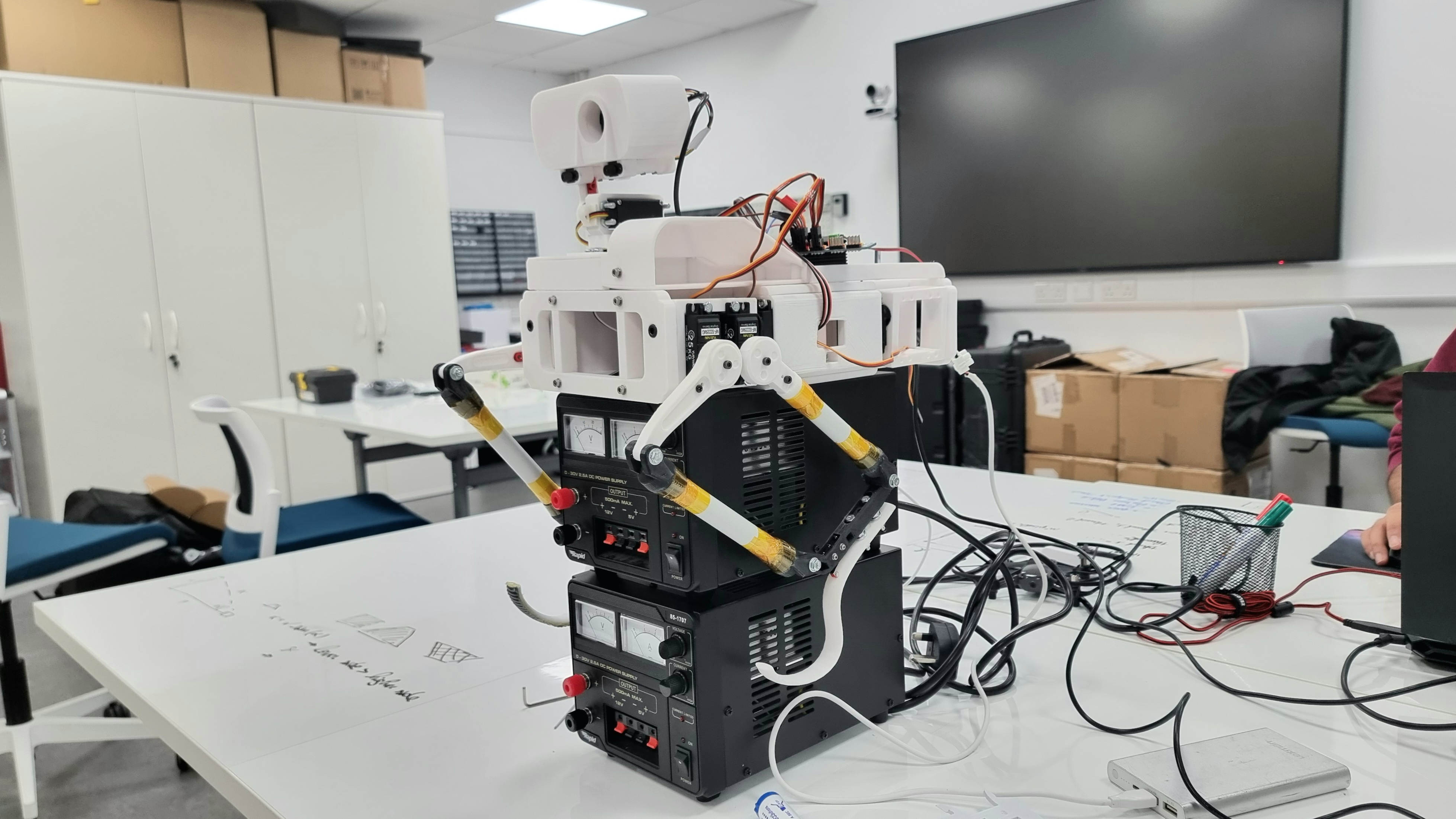
Between the 6th and the 16th of November, I worked on the control of the legs. The first step was to ensure motors were actually powerful enough to lift the entire body of the rover. Motor strength, however, is not the only parameter affecting this test's success or failure: the length of the leg joints also plays an important role. If the femur or tibia is longer than the other, it can affect the torque required at the joint. Generally, a longer lever arm decreases the torque at the end of the joint. Therefore, if the femur is longer, it may require more torque to move the leg than in a situation where the femur and tibia are more balanced. A combination of the design I was initially using, plus a bottleneck caused by thin cables that were limiting the current draw, was not allowing the robot to lift itself. I use four motors that run between 5 -7 Volts and 1 - 2 Amps powered by a 20000 mAh power bank with an output current of 3 Amps. Nominally, this should not be enough to power four motors. However, good management of the current draw obtained through software allows motors to run anyway. Some suggestions for testing such a configuration are using suitable wires (possibly not jumper wires for connecting the motors to the battery), trying several iterations to find the best leg joint design, recording videos, and taking photos and notes about what you are doing. This helps keep track of your progress, as well as what is not working.
Thank you!
Designing, building and testing Continuity requires a lot of effort and I invite you to be a part of it! Your support can fuels the Research, allowing me to test new technologies and materials, enabling exploration of new horizons. Every donation, no matter the size, is really appreciated. By contributing, you're not just funding Research; you're becoming a cherished member of a community, making this project come true.
ALL FUNDS raised are used for this Research. I really appreciate any help you can provide 🙏🏻 . https://gofund.me/55b980c0
Quick facts!
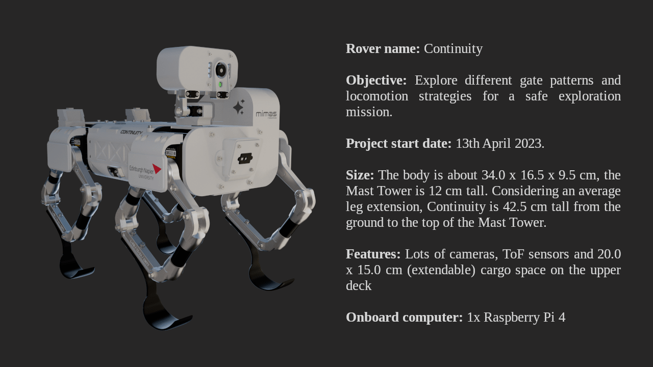 Continuity is designed to be as compact as possible, taking inspiration from already-existing quadruped robots, and integrating specific features of planetary rovers.
Using a small and relatively cheap robot for planetary exploration would guarantee access to inaccessible areas, like rocky slopes, craters and caves. Ideally, if a group of "Continuity" rovers cooperate in a multi-robot mission, it would be possible to sacrifice one of them for a hazardous mission, while keeping the others safe.
Continuity is designed to be as compact as possible, taking inspiration from already-existing quadruped robots, and integrating specific features of planetary rovers.
Using a small and relatively cheap robot for planetary exploration would guarantee access to inaccessible areas, like rocky slopes, craters and caves. Ideally, if a group of "Continuity" rovers cooperate in a multi-robot mission, it would be possible to sacrifice one of them for a hazardous mission, while keeping the others safe.
Imager camera and TOF sensor
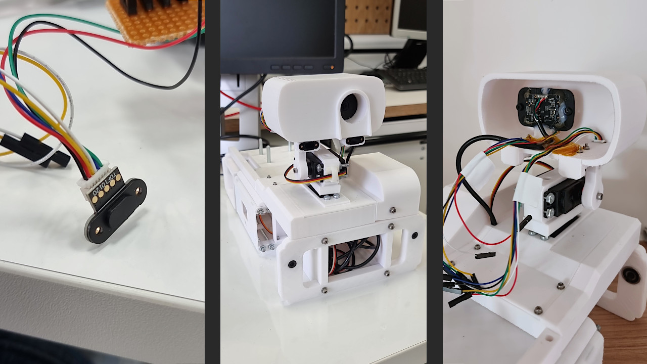
The Imager, that is to say, the top part (or head) of the Mast Tower is the key that justifies the existence of the tower itself: elevating the main rover camera, giving it rotation freedom in all directions. At its current state, Continuity's Imager is equipped with a 1080p camera and a couple of 10120 TOF sensors. A TOF (Time of Flight) is a sensor commonly used on drones due to its extremely low weight. It allows the rover to estimate in real-time the distance between the sensor and an object counting the time light takes to go back and forth from it. Since its precision is not always ensured, I installed a couple of them for redundancy and to get an average of their measurements, obtaining a more reliable value. There is still plenty of space inside the Imager, but this is fine because this will not be its final look, and many parts still need to be improved: for instance, the height of the Mast Tower, which risks being too high compared to the rover centre of mass.
Mast Tower base: 270° servo motor
Five days after assembling the first rough version of the rover body, I came up with a way to reduce the Mast Tower weight and improve, at the same time, its precision. The 3D-printed gearbox has had several backlash problems since the beginning. Additionally, it was heavy and unnecessarily complicated. As discussed, the giant steel bearing used as part of the azimuth rotation mechanism represented a severe issue due to its weight. I decided to try a completely different approach, using a 270-degree servo motor instead. This limits the azimuth rotation, but the precision is significantly increased since the servo uses a potentiometer to rotate to an always-known position. Moreover, there's no need to point the camera towards the side module, located on the LHS of the Mast Tower, since there's nothing to see there.
Rover body first assembly
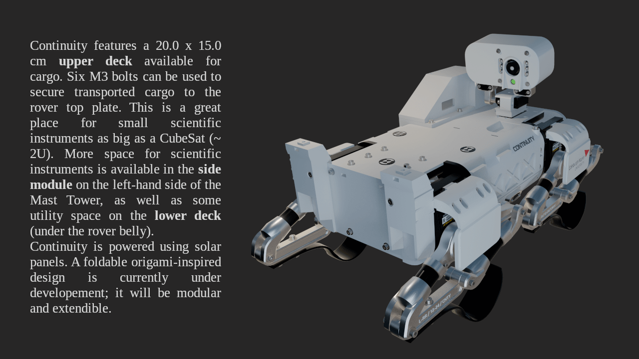
The rover body is fundamentally made of five parts: the upper and lower deck, the legs assembly, the mast tower and a side module. At the current state of things, the structure is very unbalanced due to the mast tower azimuth motor bearing. However, printing three out of five parts helped me better understand the rover assembly, all available spaces for electronic components, where to pass the cables to power the motors, etc. That said, the mast tower base must be lightened.

The motors I used for the hip joints are a serious weak point of the design since leave a lot of space between pieces and increase the overall weight of the robot. Surely, they are useful in increasing mobility, and adding a degree of freedom, but this might not be a sufficient reason to keep them in the final design.
Welcome! This is the logbook for "Continuity" project.
Hi, I'm Giorgio, a student at Edinburgh Napier University. In July 2023 I got my Bachelor's Degree in Mechanical Engineering, and now I'm carrying out a PhD Research focused on a Planetary Robotics project. The Research aims to "explore different gait patterns and locomotion strategies to identify the most significant parameters affecting an optimal gait selection". The Research is conducted on a specially designed walking robot, designed from scratch and Open Source. The title project is "Legged excursion on unstructured surfaces", and the robot/rover name is Continuity!
This website is a roadmap blog / logbook to keep interested people updated on every step of the Research. For practical reasons, the blog writing format is unformal, making it more accessible and understandable for readers, and easily updatable for me.
- University email: 40445471@live.napier.ac.uk
- Personal email: giorgio@clivio.net
- LinkedIn: Giorgio Clivio
All funds raised are used for this Research. I really appreciate any help you can provide. https://gofund.me/55b980c0
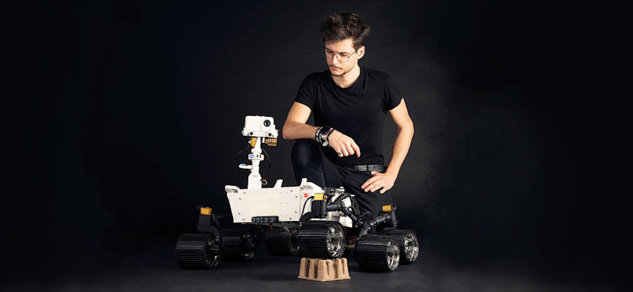 This is me with Mimas Rover, a Mars Rover replica that I built as Honours Project at ENU.